5/28/19 MW wrote, "I just finished installing axle spindle seals on both sides of my GC2400. I read your page detailing the step by step process and the project went perfectly. Thank you for taking the time to document the repair, it was a reference for me more than once! The only part I found difficult was removing the female side of the seal, your tip of cutting it with a chisel worked great. I felt confident starting the project because of your detailed instructions."
March 2016 - Buying Manuals
The
first problem I worked after purchasing the tractor wasn't really a
problem. I just wanted owner, parts, and maintenance books.
AGCO (who purchased an owns the Massey Ferguson line) has an AGCO
on-line parts manual (login as guest to view books), so there's
really no reason to buy the paper parts manual.I ordered 4 paper books, which immediately highlighted the fact that there is a serial number break in the GC2310 series. They refer to it as "N 25201", which means any tractor with that serial number or after has a different parts catalog and a different operating manual. To interpet that serial number, you have to add the common letters. "JNA 25201" is what you would find on your tractor. The tractor serial number is behind your left heel; don't confuse that with the frame serial number or engine serial number. My serial number is JRAxxxx, and because R comes after N, I have the later model. An easy way to tell the difference is that the newer serial numbers have a tachometer around the hour-meter.
Here are the paper book part numbers for a GC2310 with a serial number JNA25201 or later. Check the AGCO parts web info if you want ot confirm - be sure to choose the English lanuage if that is what you want. If you order from AGCO, you can get DVD versions for a few dollars cheaper with noticeably less shipping cost.
Operating Manual - 1449927M1, $17
Service Manual - tractor 4283003M1, $29
Service Manual - engine 4283035M2, $17
Parts Manual - 65179M92, $28
Service Manual - tractor 4283003M1, $29
Service Manual - engine 4283035M2, $17
Parts Manual - 65179M92, $28
April 2016 - Fluids
After researching different options, here's what I purchased to change expendables. These are alternatives to the AGCO filter part numbers. I like to do this up front so I know the service intervals start from zero.Oil
Filter - FRAM PH4967/4767, NAPA 1360, WIX 51360
Engine Oil - Shell Rotella T semi-synthetic 15W-40 (white bottle)
Hydraulic Filter screw-on - AGCO 4265229M91 (no alternative found yet, $29)
Transmission and accessories hydraulic fluid - Coastal Multi-Trac in the green 5-gal bucket, $46
Front axle fluid - same as transmission hydraulic fluid
Fuel filter - FRAM C7516 $15, NAPA 3262, WIX 33262
Air filter - NAPA 9691, WIX 49691
Engine coolant - commerical 50:50 mix from car parts store
May 2016 - Replace Axle
Steering Spindle Oil Seal
I
checked in the front axle fill cap on the left side and the internal
gearing looked wetted with oil, but there was no standing oil.
It's suppose to be filled up 1/2 the height of the axle, so I added
fluid. Within a day, it had leaked out the right steering spindle
onto the garage floor, so I knew that the seal needed to be replaced
(part number 4265156M91, $30.85 from Jacks Small Engines
https://www.jackssmallengines.com/jacks-parts-lookup/part/4265156m91).Others have documented replacing the seal for a MF 1553 and MF GC2300.
Right-Click
(dual-click on a Mac) any picture to see a
full-size view or download.
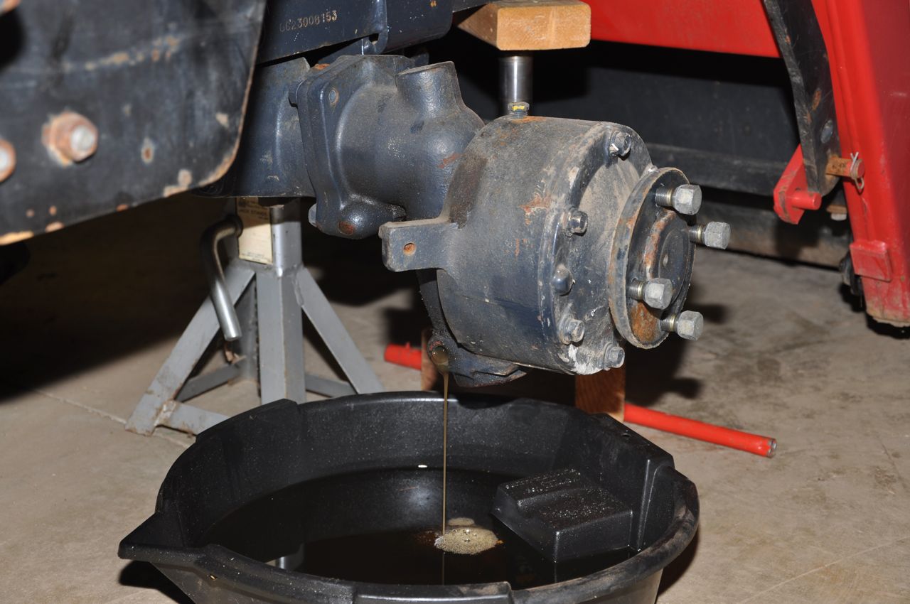 Overall work area. Right front
tire removed. You can use the front loader bucket to lift the tractor
and then put a
jack stand under the frame. Final gear housing hydraulic fluid is
draining out.
|
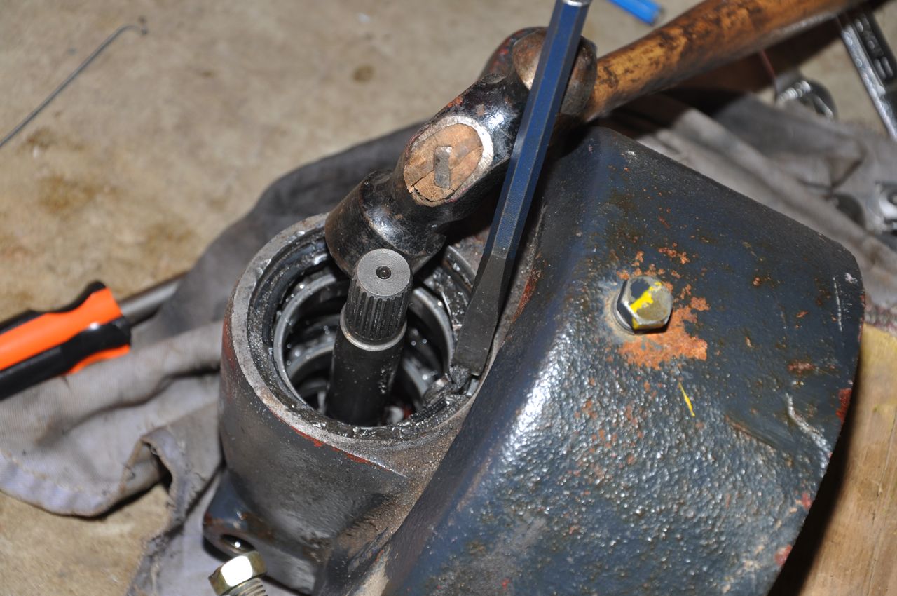
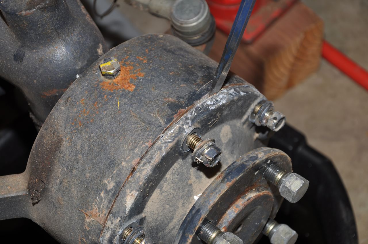 With
all the bolts loose, split the gear cover from the main housing. I
gently chiseled around the entire seam to break the silicone seal,
but later realized there are notches at the seam on the left and
right side (just out of this picture) to push in a screwdriver to wedge
them apart.
|
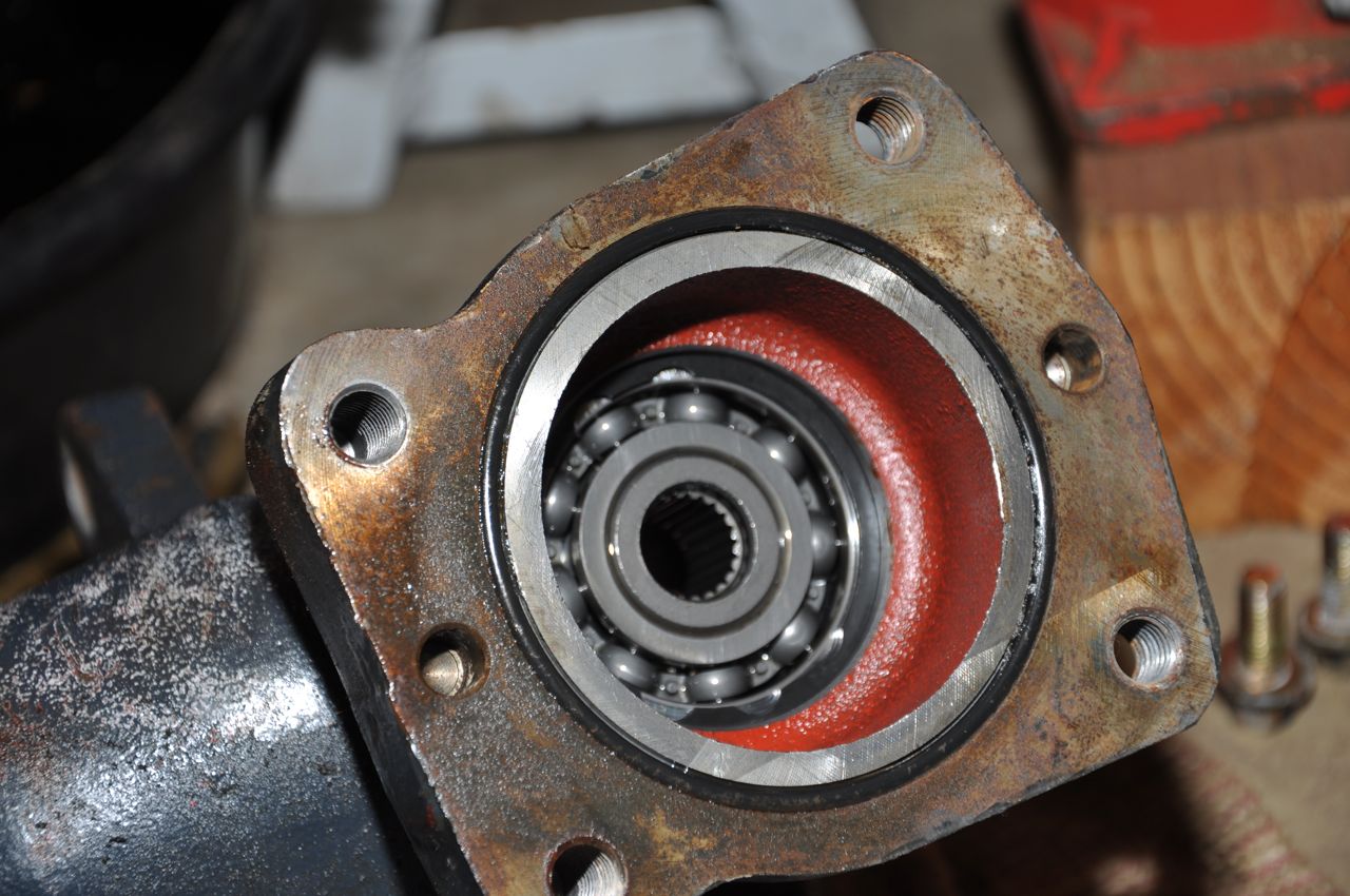
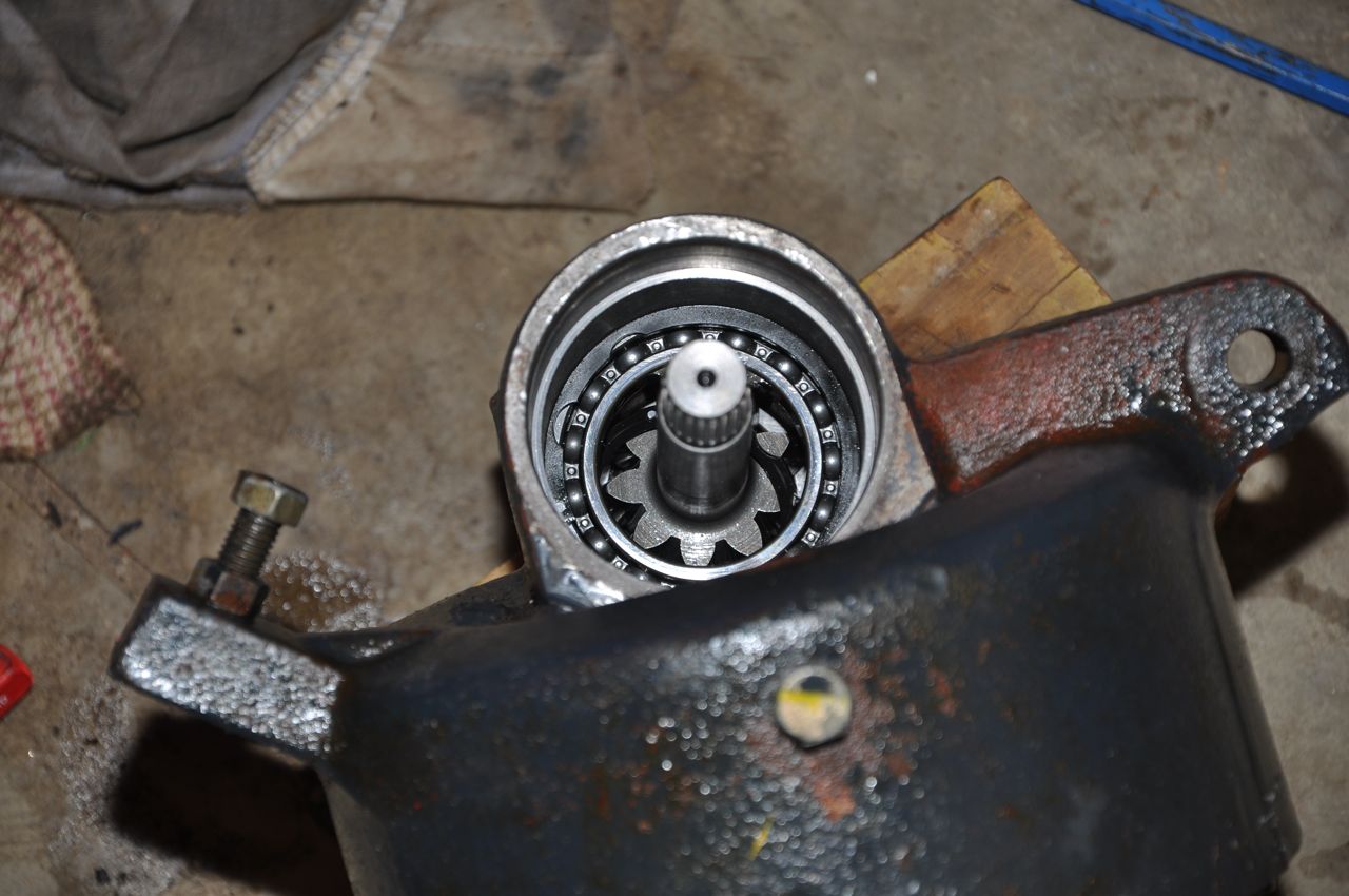
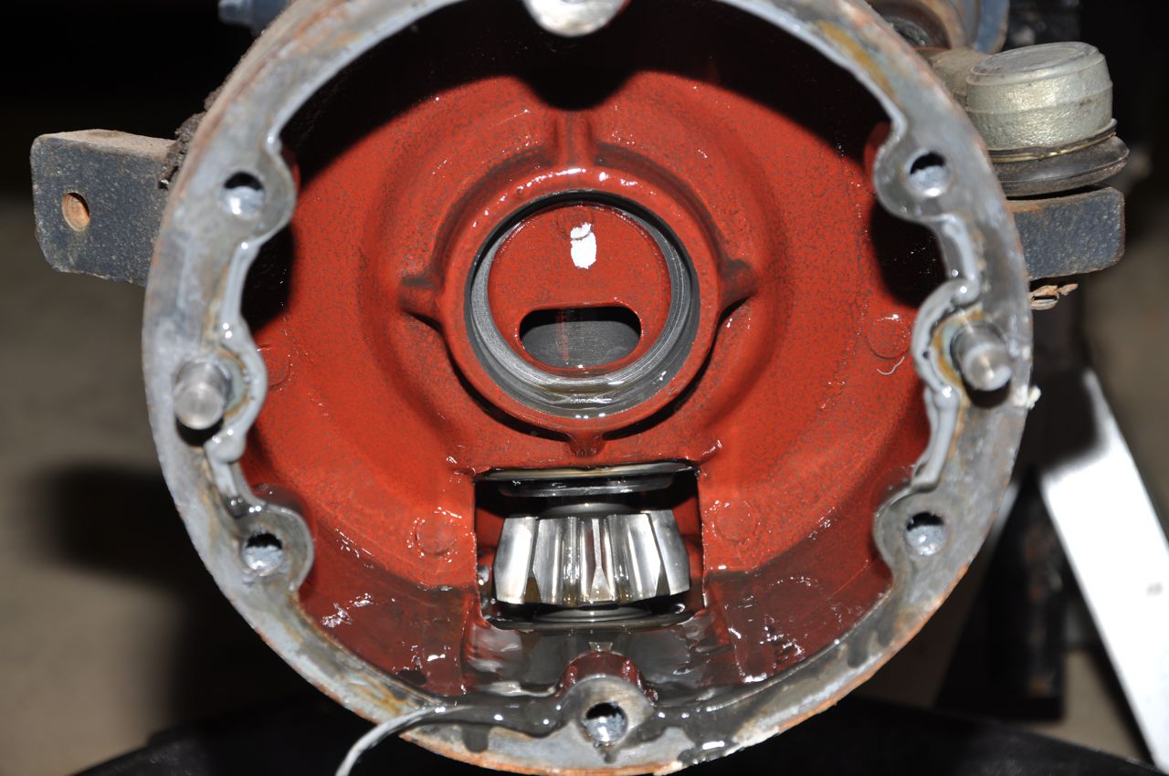 Looking
inside the final gear
housing. The central bearing comes out with the gear. Look
carefully on top of the other little gear and you can see the snap
ring. After 870 hours of operation, there was silt collected
along the bottom of the cavity. Two pins support and allign the cover.
|
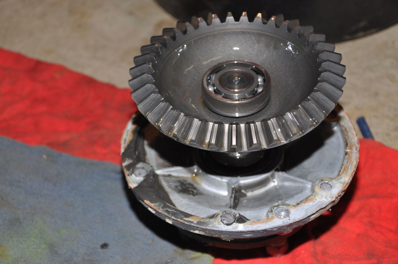 Final
wheel gear with more silt
collected along the bottom edge (left of photo). Clean out silt
and clean the mating surface, but otherwise, there is no need to do
anything with these parts.
|
 You may be able to replace a spindle
oil
seal without removing the 90 degree angle housing.
However, 4 bolts and an O-ring seal is pretty easy to take apart and
put together. It slips off the spline shaft easily once the four bolts
are removed and the tie-rod taper bolt is separated. You may be able to replace a spindle
oil
seal without removing the 90 degree angle housing.
However, 4 bolts and an O-ring seal is pretty easy to take apart and
put together. It slips off the spline shaft easily once the four bolts
are removed and the tie-rod taper bolt is separated. |
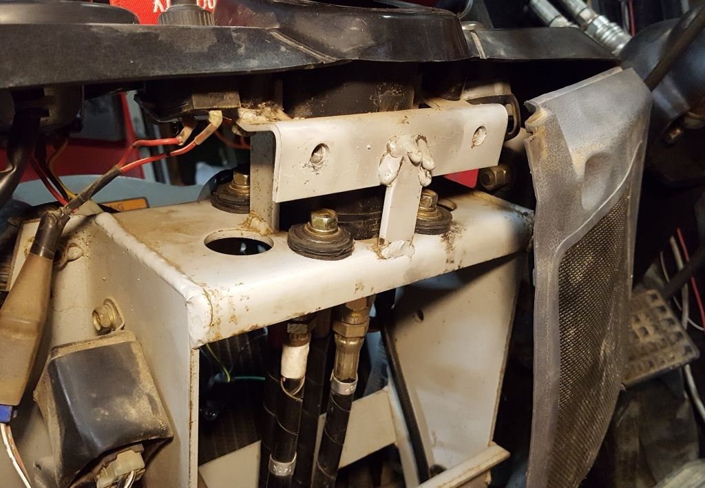
 Top
of the 90 degree gear housing. I cleaned 10 years and 870 hours of crud
off the metal surface and cleaned out the o-ring. 4 bolt holes and 2
alignment pin holes.
|
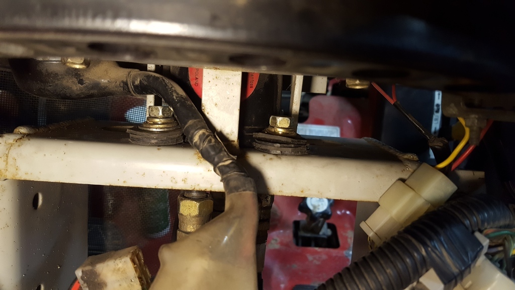
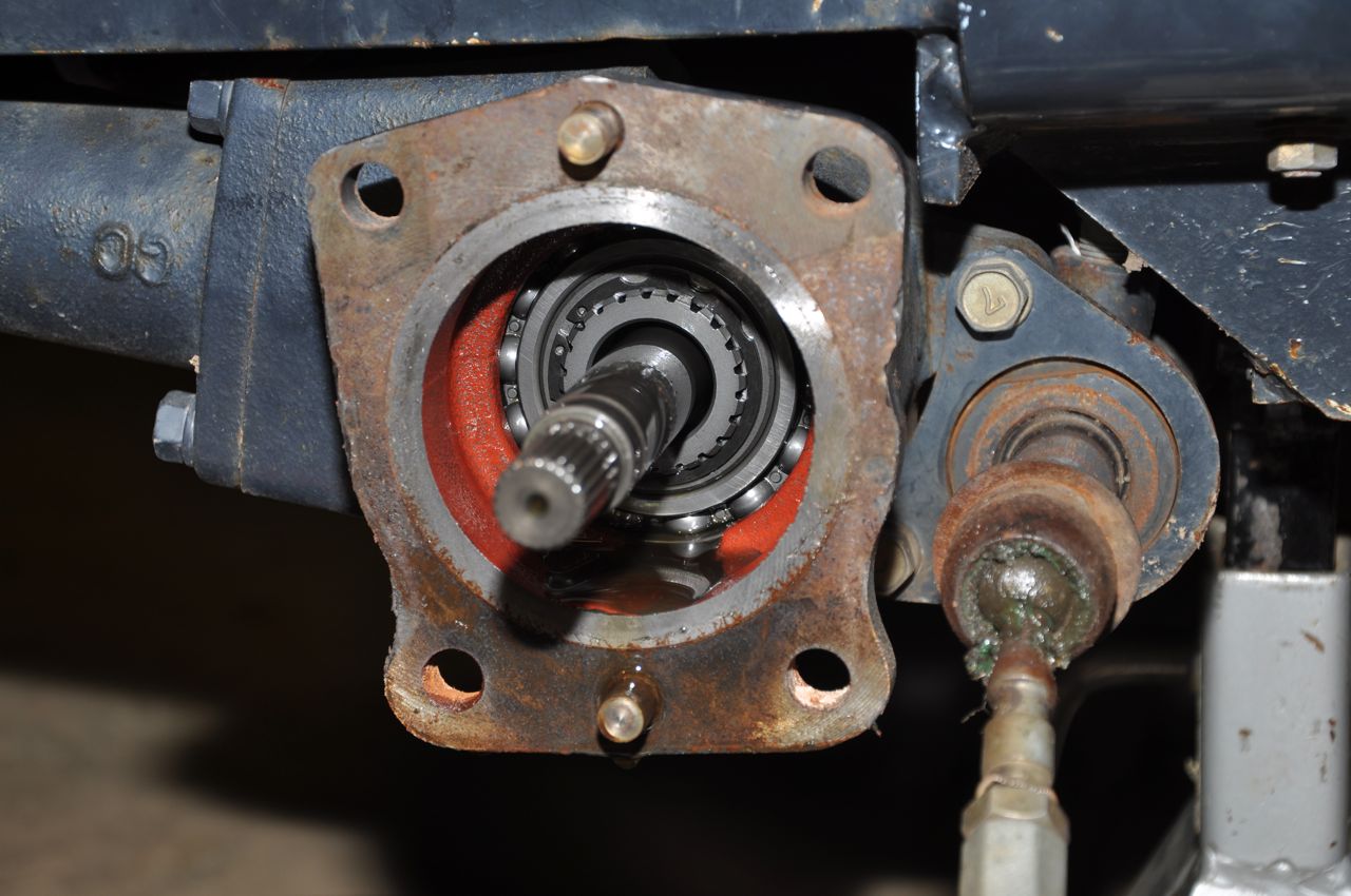 Drive shaft extending out ward.
It's loose and can be easily pulled or fall out; I left it sitting
there. Notice the bad tie rod
ball I smeared some grease into. I ended up replacing these, too.
|
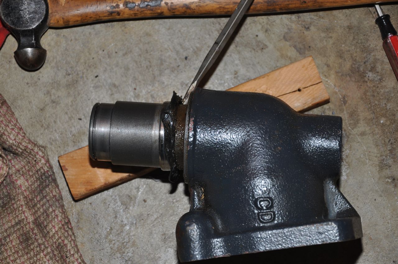
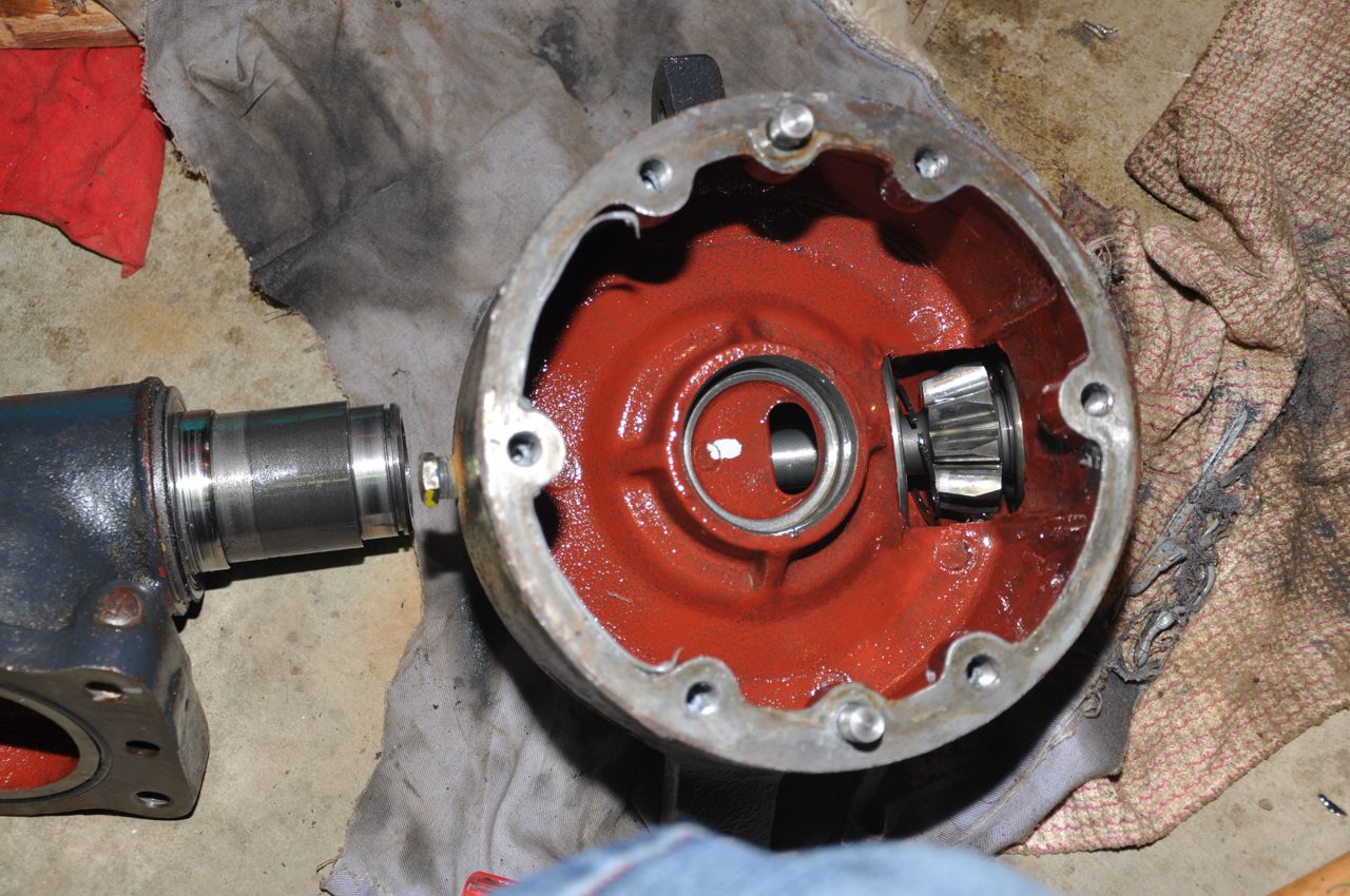 Unseat
the snap ring by the gear and the final gear housing drops off the
spindle. You can see the oil seal sleeve on the spindle (shiny
reflected part).
|
 To
remove the inner seal, I cut the metal band with a cold chisel and
pried it inward toward the center. Be careful not to damage
the metal surface of the shaft housing.
|
 After removing the inner seal, I
cleaned the 90 degree and final housing and bearings with copious
amounts of solvent.
|
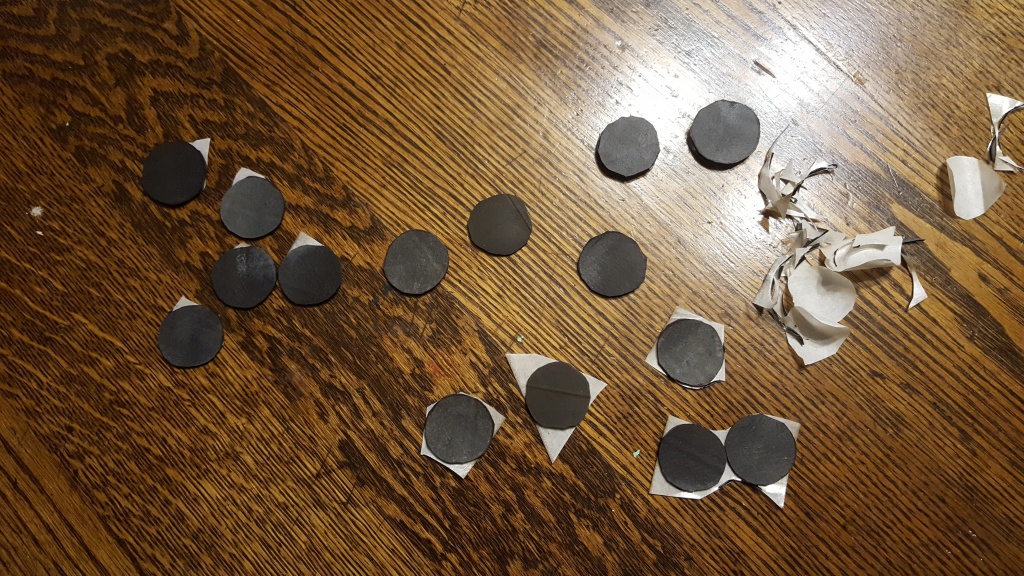
 The
oil seal has two parts. This shows removal of the collar sleeve, which
was a tight rusty fit. Lots of prying with a screwdriver around and
around.
|
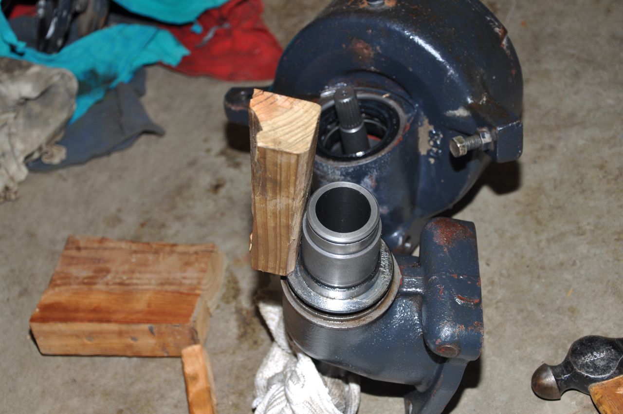 I
installed the new collar by lubricating and carefully tapping around
and around the
shaft with a block of wood and re-applied vaseline to lubricate the
seal.
|
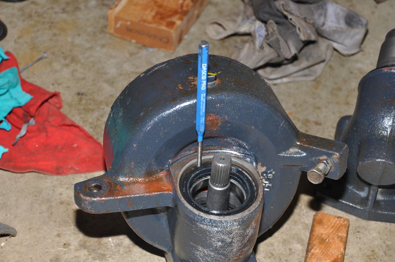 The
inner seal needs to be set below the surface of the metal, so I used a
flat faced punch that was sized to not crush the rubber flange. I went
around about 4-5 times before it was set all the way.
|
.
|
.
|
In order to work on the front axle, you need the wheels off the ground. You can use the bucket to lift up the front of the tractor and then put a jack stand under the frame near the front axle. Use a 19mm socket to remove the wheel studs and remove the wheel.
To open up the final gear housing, I worked a chisel around and around the silicon seal. If you look carefully there are notches on the left and right side in order to catch a screwdriver blade and pry open the seal. Also remove the outer tie-rod taper bolt so the final wheel housing can come totally off the tractor. Look in the housing just above the small gear. You can see the snap ring that must be strentched open and removed from its notch. My snap ring pliers spread the ring barely far enough. The final gear housing will drop away from the shaft.
You could replace the seal without removing the 90 degree gear housing. It depends on the condition of the seal sleeve installed on the upper part of the shaft. If it's really stuck or rusted into position, you'll want to be able to work around all sides of it and that is way easier if the 90 gear housing is not connected to the tractor. So, remove the 90 degree housing if you want.
The replacement rubber seal is a 2-piece thing. You have to remove one piece from inside the lower wheel gear housing. You have to remove the other collar piece from the outside of the upper shaft arm. It's easiest to understand how the fit together by looking at the new seal you purchased and pull the two pieces apart and inspect them. Both of the pieces from my old seal were very tightly installed and I needed to use a chisel to break the metal part of the oil seal before pushing / sliding / twisting them to remove them. If you do this, be careful to not chisel or dent the metal underneath the seal piece. After both pices are removed, clean everything up with solvent and confirm you haven't damaged the shaft or bearing housing.
Putting the new seal in place (both pieces) involves lubricating it and pushing, pressing, or gently tapping it them into position. Work around and around with little taps with a hammer and it goes on pretty easily. Just be patient. Re-lubricate both halves of the seal and put the spindle back into the wheel gear housing and hold it in position while re-installing the snap ring. With a worn set of snap-ring plier tips, this proved impossible. I had to purchase new snap-ring plier tips that are the right size for the snap-ring hole and have non-worn edges.
To reconnect the final gear exterior cover, I scraped off all the old silicone rubber, filed off one little blemish, and touched up the entire surface with emery cloth. I cleaned everything with gasoline and then rinsed the surface with acetone to remove any oily residue. I applied silicone rubber as a gasket and re-assembled it.
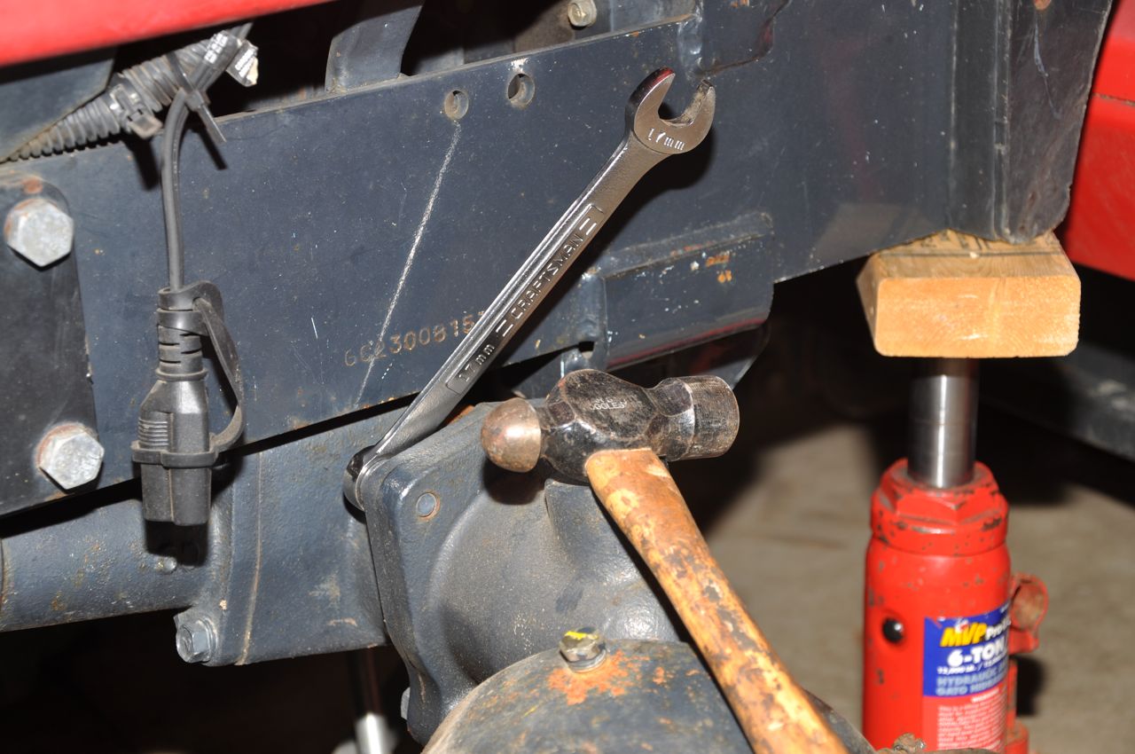
I measured the bolts as 9 mm in diameter. The service manual identifies torques for only 8 mm or 10 mm bolts. I used the high end of 8 mm as my target and torqued everything to 20 ft lbs. If you pulled off the 90 degree gear housing, there is no way to get a torque wrench on the four bolt heads. I used a 1' long open end box wrench and pulled the wrench with a 20' fish scale in order to get 20 ft lb of torque.
I put hydraulic fluid into the right gear housing through the top bolt hole in case there was an air bubble trap somewhere, and then added more in the left axle fill cap up to a half-filled axle. Side note - after about a day of work, I noticed the left spindle was starting to seep oil out. Uggh.. I think I need to go replace the other seal, too. I think the right leak was keeping the fluid level low enough to not affect the left side, but with the right side fixed, the fluid level stays high enough to make the left leak visible. I will have to order another seal and repeat in the near future.
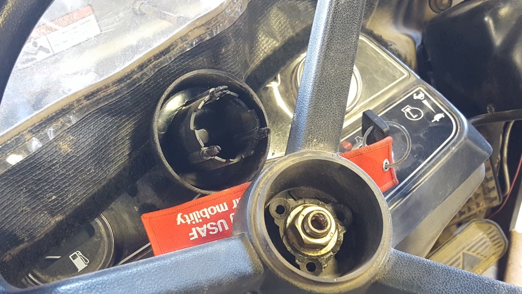
May 2016 - Replace Steering
Rod Ends
The right
steering rod end had no rubber boot on the inner ball joint and the
ball and joint were totally rusted and very loose. The left one
was badly cracked and the inner ball joint was rusty and loose. I
wondered if I could operate the tractor this way until one of the ball
joints just popped out. For a car, this would be bad because the
toe-in would wander around and it would probably make bad rattling
noises when on the road and would probably wear out the front tires
really quickly. However, a tractor is bouncing around on uneven
loose surface most of its life so I'm not sure the tires would ever
know the difference. Eventually,
I decided to buy new ball joints so as to not let little maintenance
items build up. Turns out you can't buy just the inner ball joint
any more. That part has been superceded by another part, which
has been superceded by another part. The final part (7069209M91,
$73) is an aggregate kit that includes everything outboard of steering
rod out to the tie rod tapered bolt. It does not include the big
flat washer where the rod end screws into the hydraulic piston and it
does not include a lock washer or castle nut for the tapered bolt.
Eventually,
I decided to buy new ball joints so as to not let little maintenance
items build up. Turns out you can't buy just the inner ball joint
any more. That part has been superceded by another part, which
has been superceded by another part. The final part (7069209M91,
$73) is an aggregate kit that includes everything outboard of steering
rod out to the tie rod tapered bolt. It does not include the big
flat washer where the rod end screws into the hydraulic piston and it
does not include a lock washer or castle nut for the tapered bolt.Spoiler alert: the cotter pins and 10mm-1.25 castle bolts on the tapered bolt were very rusty. I ended up having to get new of both. The hardware store sold a package of 100+ miscellaneous cotter pins that notably did not have the one size I needed (3/32" diameter an inch or longer), so I drove back and bought the package of the exact size. A new castle bolt was made out of a normal grade (hardness) nut by cutting slots with a cutoff wheel grinder. I will have to watch these and see if the nuts are too soft, or loosen.
When removing the tie rod, if the taper bolt is stuck tight, consider using an air chisel. No! don't hit any tractor part with an air chisel. Back the bolt off until it's flush with the end of the bolt. Then use a thick aluminum bar or plate between the nut and bolt and the air chisel. The softer aluminum takes the hammer blows and transfers the impacts to loosen the bolt without damaging the bolt or nut. This method has reliably removed tie rod end bolts in every vehicle I've tried it with.
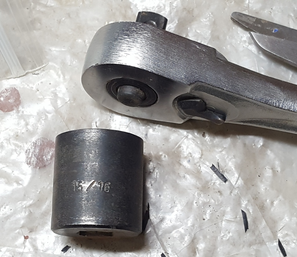
The tie rod ends screw into the ends of the hydraulic actuating rod, separated with a large flat washer that prevents the tie rod from crushing in against the oil seal when the steering wheel is turned hard left or right. In order to screw / unscrew these connections you have to be able to grab the rod ends and the rods with a wrench and turn about 20 ft lbs. The flat sections provided to do this are very narrow, so I had to grind down my tools to make them fit. Two "special" tools are required:
A
narrow 19 mm open end box wrench for the flats on the stainless steel
hydraulic drive rod. A wrench of this size was not economically
available alone, so I picked up an entire set of metric wrenches for $9
from Harbor Freight. I'm not sure their tools are hard or
accurate enough for regular commercial use, but for an open end box
wrench that will get ground down and used once every 3 years, I
appreciated the lower price.
A narrow 28 mm open end box wrench for flats on the tie rod ends. I could not find a 28 mm wrench for sale other than in a $50 kits, so I used a 10" crescent wrench, which opened jaws just enough to fit. I picked up a $6 version from Harbor Freight because I had to grind down the width of the jaws to fit onto the narrow flats of the tie rod ends, and didn't want to grind on my main shop tools.
A narrow 28 mm open end box wrench for flats on the tie rod ends. I could not find a 28 mm wrench for sale other than in a $50 kits, so I used a 10" crescent wrench, which opened jaws just enough to fit. I picked up a $6 version from Harbor Freight because I had to grind down the width of the jaws to fit onto the narrow flats of the tie rod ends, and didn't want to grind on my main shop tools.
Because there was no rubber left on the old rod ends, I could use a fat-jaw pipe wrench to take them apart. Turning in opposite directions, one would let loose first. Luckily the left one came off first, exposing the flats on the end of the stainless rod. I did not have to grind down the thickness of my 19 mm wrench. To unscrew the right tie rod, I used a pipe wrench while holding the stainless rod on the other end with the 19 mm wrench.
To re-install the tie rod ends into the stainless steel hydraulic rod, I couldn't use a pipe wrench because it would have crushed the rubber seal. Instead, I used the narrow-jaw cresent wrench to fit over the tie rod ends without interfering with the big flat washer. I put the right rod end on first using the stock 19 mm wrench. To install the left one, I had to use the narrow 19 mm open end box wrench to not interfere with the big flat washer. I pushed what felt like about 20 pounds on the end of my approximately 1 foot long wrenchs.
I put the taper bolt castle nut back on to 20 flt lbs with a torque wrench and then backed off only enough to slip a cotter pin through the first available nut slot.
I preset toe-in by counting tie rod end thread grooves on the old rod ends. Mine had 3-1/2 threads exposed on each side. After putting the tires back on the tracter, I checked alignment for the spec'd 2-6 mm of toe in (front of tires closer together than the rear of the tires). Nothing fancy, just a tape measure held against the tire surface at mid-axle height measured between two 2x4 sections held against the outside of the tires (someone helped me on the other side of the tractor). I found about 1 mm of toe in with weight off the front wheels. I will check and adjust again after the hardware has settled for a week or so.
Summer 2017 - Removed the
biggest stump
The
prior year, I cut down a big leaning tree. I did use the backhoe
to try digging out some of the stump, but didn't get very far.
All winter and spring the stump stayed in the backyard and had a moat
around it whenever it rained. I knew I'd have to get it out,
eventally. The tractor in the picture is 4' wide. The stump is
slightly wider and taller. It was a BIG stump. 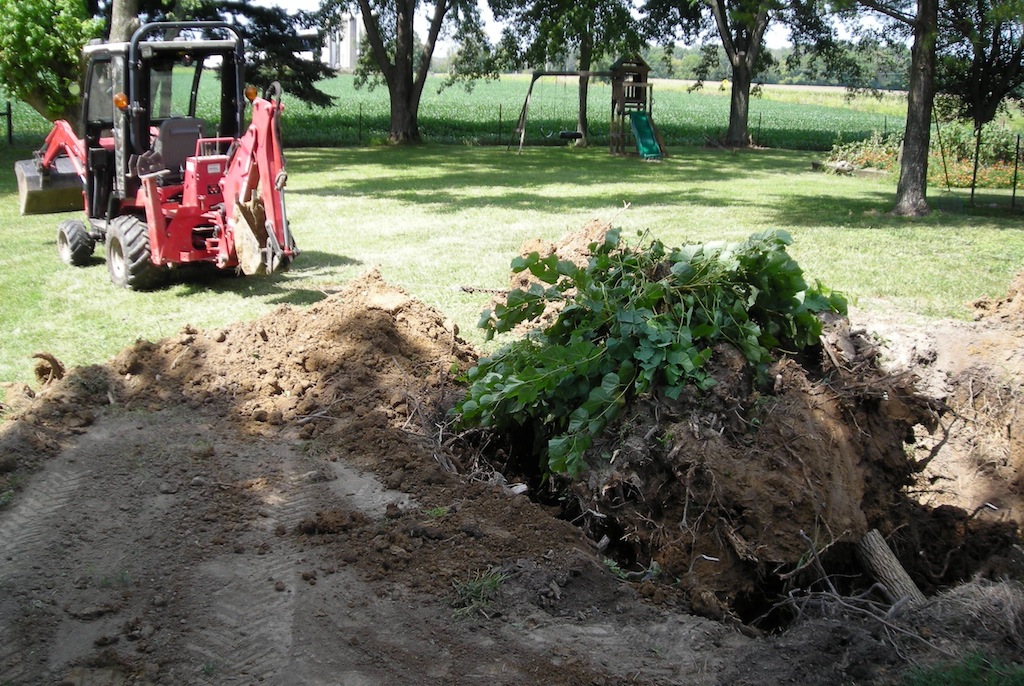
At first I was coming at the stump straight on with the backhoe and digging from several positions around the stump. I just couldn't get the depth required. I ended up modifying my technique by digging deep 4' trenches on the left and right side of the stump instead of in front of it. I did this from 4 positions around the stump.
Very soon I had a pillar of dirt in a deep hole. When I stood in it, I was up to my chest in dirt. I tried pulling the stump and dirt pillar over using a full-size van, but the rear wheel just spun in the grass. I hooked up a chain to the tractor on the lowest point below the rear wheel axle (for leverage) and in 4WD and tugged and relaxed over and over - maybe 20 times and finally the pillar of dirt tipped over, but there was no way I could pull or lift or drag it out of the hole. If I released tension, it immediately tipped back.
I used a log about 8" in diameter to block the stump, as shown in the picture. I put a little dirt under the stump and then removed th e log. Tthen I pulled the stump over the other way pulling from the other side, and added a few shovels of dirt under the stump on that side. After about 15 back and forth pulls, taking several hours, I slowly put more and more dirt under the stump until it was all the way out of the hole--or more accurately, the hole had been slowly filled in under the stump. I tried pushing or lifting it and that was a total no-go. The stump is not moving. We'll burn spare sticks and brush under the stump for several months -- maybe even into next year. But eventually it will be gone. What's interesting is that the very heavy clay dirt is cooked by the fire and turned into firebrick. Every once in a while I go chip some off and do another fire. Note - finally burned it all gone in November of 2018.
May 2018 - Left Front
Steering oil seal
I need another
steering shaft seal
(4265156M91). I'll order from McFarlane Mfg, Saulk City,
WI (JacksSmallEngines.com said they don't sell
Massey parts any more). When the parts arrived, this worked the same as the right shaft seal documented above. However, I had a lot more trouble getting the snap ring back in place. One reader recommended channel lock snap ring pliers with a 2" throat. Available from Lowe's for just over $20. https://www.lowes.com/pd/CHANNELLOCK-8-in-Automotive-Snap-Ring-Pliers/50424410. I actually have a pair of those and they didn't work for me. I finally borrowed new tips from a friend, and that did the trick. Mine had gotten worn and beveled and the snap rings kept sliding off. Get new tips!
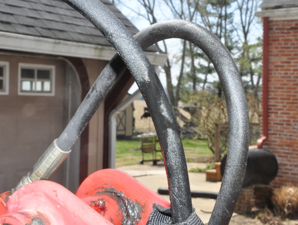
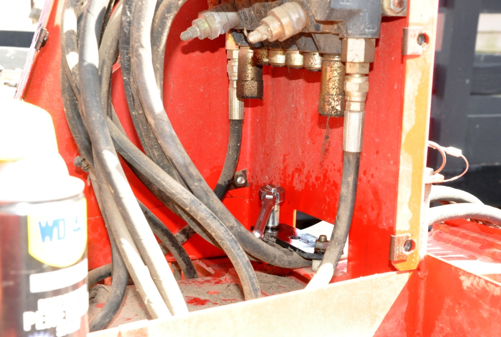
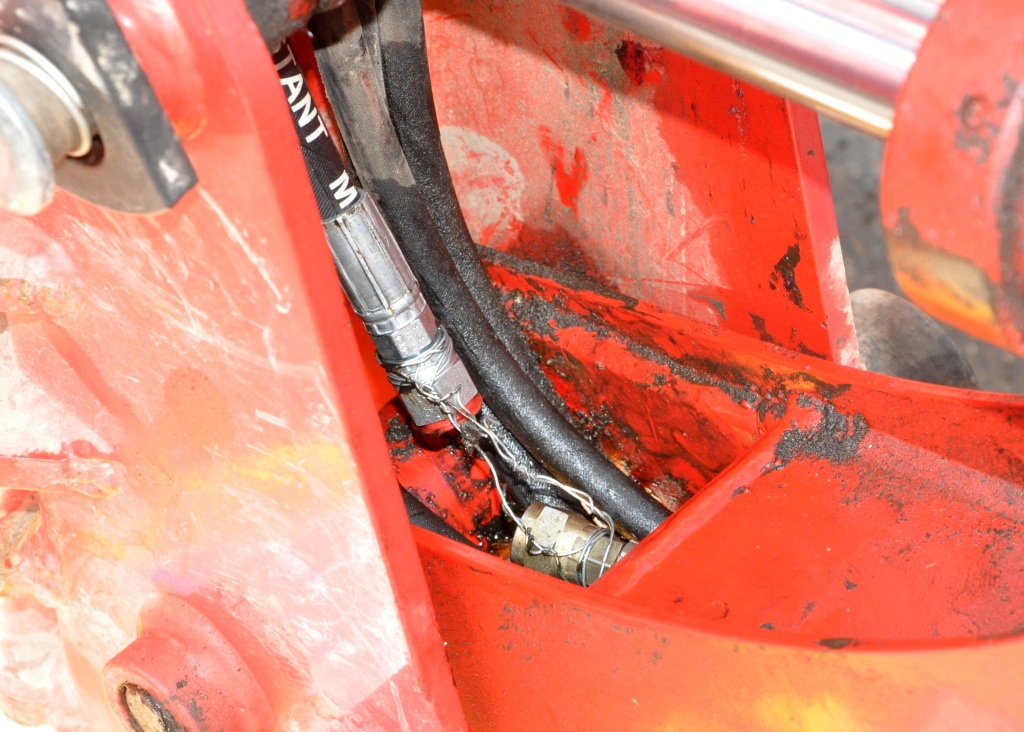
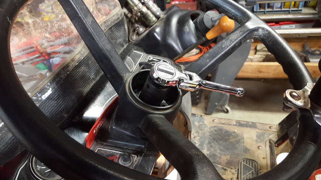
June 2018 - Hydraulic Hose
As I backed the
tractor into parking, I noticed a steady drip of hydraulic fluid coming
from the front left side. Turns out the cylinder end of the "bucket
down" line on the left side was oozing fluid out between the hose and
the crimp of the connector. Uh.. time to replace the short
flexible section of hose.The AGCO parts diagram on line shows it as a 1/4" hose 13" long, part number 71515711. I unscrewed the 1/4 I.D. hydraulic line from the cylinder side and found a male SAE O-ring Boss (a.k.a. ORB) fitting with threads that measure 0.555" across. This is the type with the O-ring around the collar, not "flat face" where the O-ring is on the face end of the threaded part. On the other end, the hose disconnected from the metal tubing, revealing a JIC female connector on the hose with 0.509" I.D. on the female thread. The JIC male threads on the metal tubing measured 0.559" O.D. across the threads. Marking a pen-line on a piece of paper and a protractor confirmed the 37 deg angle of a JIC connector (not a 45 deg JIC or 30 deg Japanese JIS).
Now I needed to match my measurements against the industry standard options. Checking a hydraulic fitting chart, I found
- JIC SAE-6 size male threads are 0.5625" O.D., with the closest alternative 0.50" and 0.75". JIC female SAE-6 threads are 0.53125" I.D. with the closest alternative 0.46" or 0.60". Since I measured 0.559" and 0.509" , my guess is they are SAE-6 with 9/16-18 threads.
- ORB-6 size male threads are the same as SAE-6 and I measured 0.555". Choices are 9/16" (0.5625") or the metric connector that looks almost identical which is M14x1.5, or 0.5512". Since the one end is SAE JIC, I'm betting the other end is not metric.
The hose is a 3000 PSI hose with an outside dimension of 0.50" and a length of 13.25" (end of metal connector to end of metal connecto). I think it's 1/4" SAE 100R17 single-wire hose with a 2" minimum bend radius. Alternately, fatter O.D. 1/4" SAE 100R16 hose might work, with an O.D. of 0.57" and a bend radius of 2" and working pressure of 5800 psi. The 100R16 doesn't seem to be much fatter, but when it's squeezed into various body channels of the tractor, the size does matter. On the backhoe, I expect the narrower 100R17 is required to get all the hoses packed in next to each other.
I called around to price a replacement.
- Advanced Auto Parts doesn't make hydraulic lines.
- Jack's
Small Engine again shows that they do carry Massey Ferguson
parts. $31.25 after
shipping.
- O'Reilly Auto Parts referred me to a sister store in a nearby city and they priced it out at $34.73 before tax.
- I priced out the assembly at discounthydraulichose.com and it came out to $29.37 after shipping.
- I checked
SurplusCenter.com and they only have stock hose lengths, but the 12"
was close. Turns out I could buy a 12" 100R17 hose with 1/4" NPT
fittings each end (916-1412),
and a 1/4" NPT female - ORB male adapter
(9-6405-6-4)
and
a 1/4" NPT female - JIC female connector (9-6506-6-4).
It
probably would add up to about 13-1/4". Total price after
shipping came out to $20.45.
One of the adapters had a 4-month backorder delay.
- Instead of the 4 month back order, at SurplusCenter, I found the 0.070" fatter 100R16 2-wire hose with different end connectors: female JIC-6 connectors (921-2212). Then all I needed was a single male JIC to male ORB adapter (9-6400-6-6). I accepted the fater 100R16 hose. Total price was $18.40 shipped.
Everything checked out fine. The only caution issue is that with an adapter on the end adding up to the specified 13" length, the non-bendable end of the hose is longer. That doesn't matter for a mostly straight run installation. For a "U" shaped installation like the loader-up hose, this probably wouldn't matter, either In this case, however, the loader-down "S" shaped installation makes the "S" stretch more than I like because the flexible rubber part of the 13" is shorter. In reality, the hose I removed was really 13-1/2" anyhow. Testing the loader full up and full down looks like it will work - it just pulls harder sideways than I would like at the full loader-up position.
Two months later, the bucket-up end of the same cylinder started oozing fluid right through cracks in the hose. I should have purchased two! Also, the "un-curl" hose on the backhoe bucket is starting to ooze fluid at the top bend of the arm. I need another 13" hose and a 128" hose. Both have ORB at the cylinder end. The bucket-up needs JIC like the one I just did. The backhoe bucket un-curl line looks like it terminates with ORB at the operator control block, too. For the hose squeezed through the backhoe arm, it will be important to get the skinnier 100R17 (0.50") instead of 100R16 (0.57").