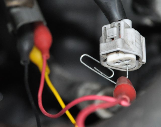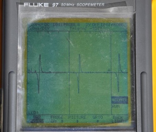
O'scope on the two pins from the a/c compressor speed sensor. Positive and negative excursions were 350 mVolts into a 1 Kohm load resister. Removing the resistor allowed the sensor to produce about 400 mV. You can watch a video of the A/C speed sensor when I manually apply +12 volts to the compressor clutch to make it run.
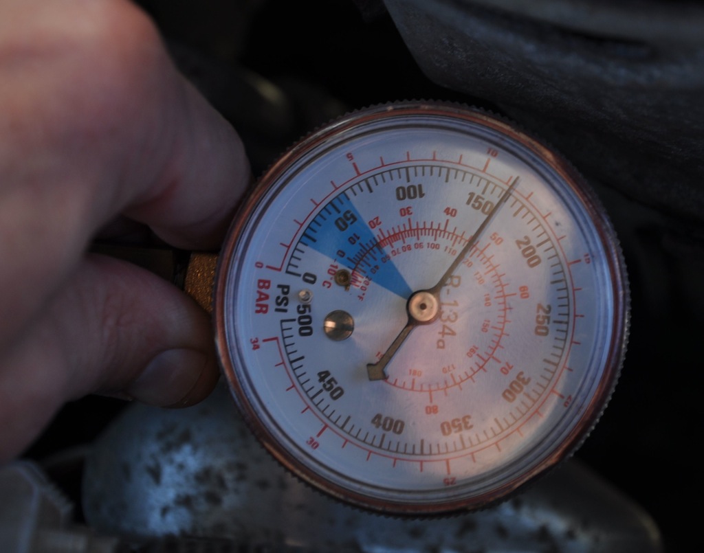
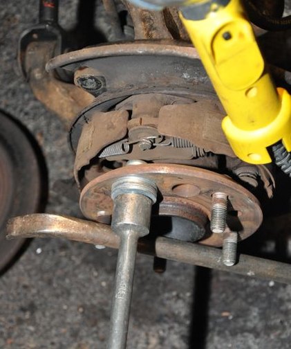
After the pressure was brought up to about 200 psi, I disengaged the clutch and the pressure settled back to about 165 psi.
I decided these readings didn't mean mutch since it was about 45 degrees F at the time.
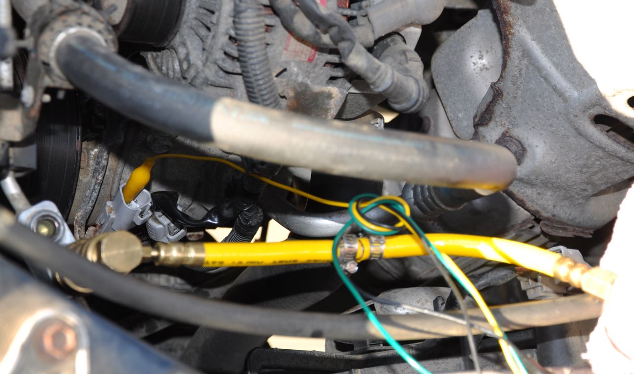
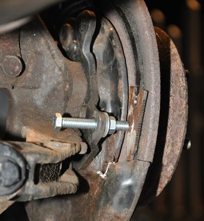
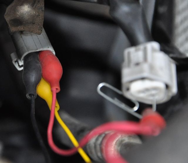
This shows the high pressure side pressure meter hooked up and a yellow test wire in place, being used at this time to energize the clutch coil.
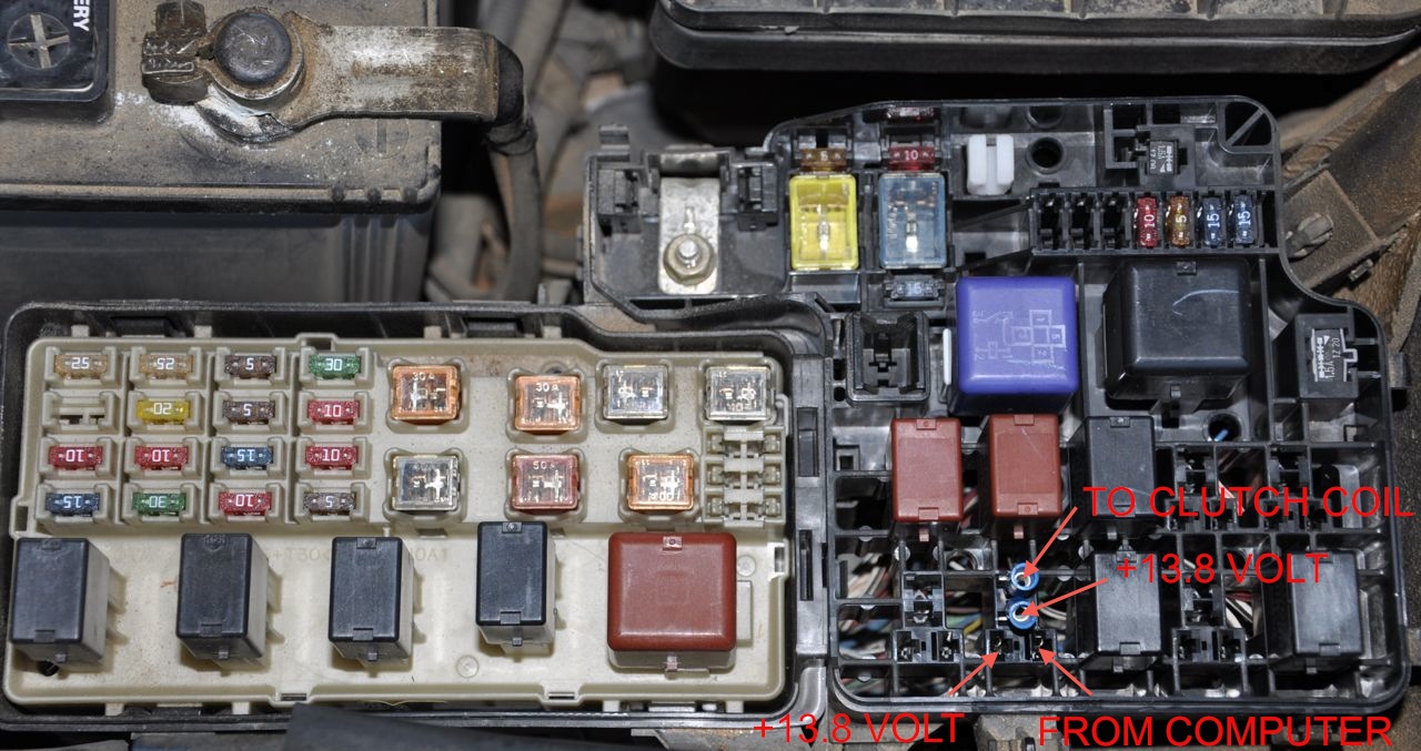
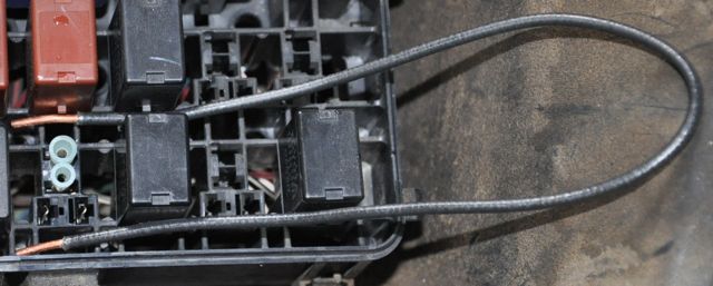
Leaning over the driver side of the front wheel looking at the relay and fuses.
I removed the relay and stuck the blue electrical connectors in place so I could grab the connection better with a pair of aligator clips.
The fore/aft terminals are the relay coil, with 12v on the forward terminal. The inboard/outboard terminals are the relay output.
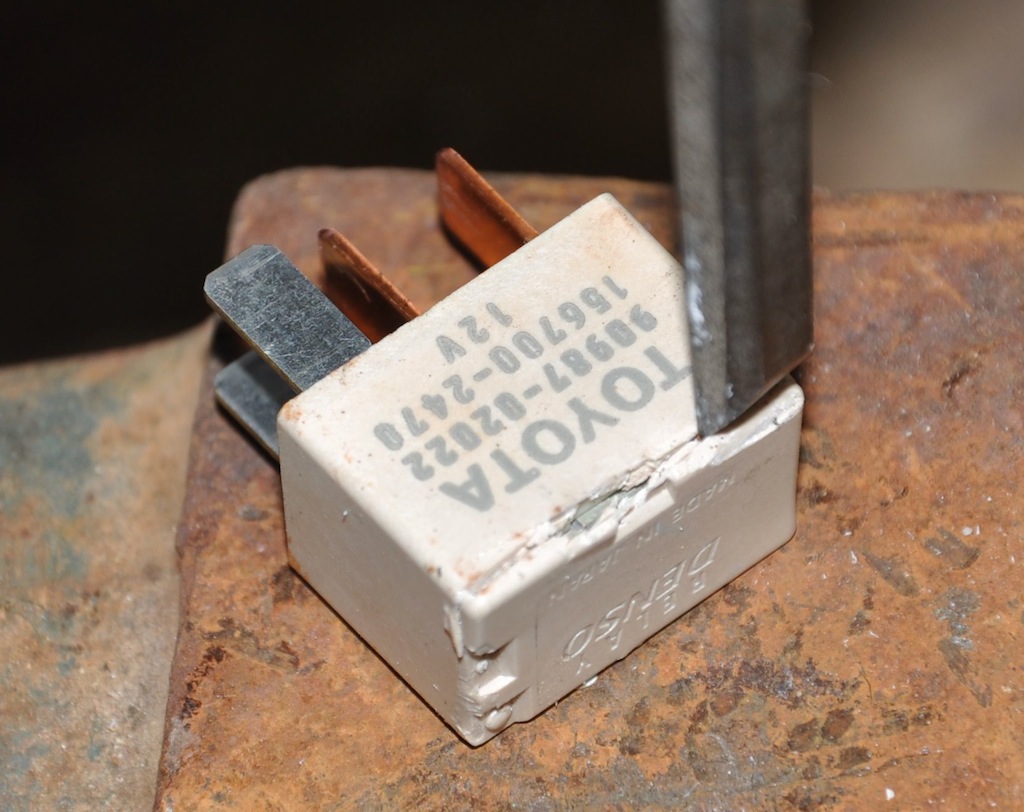
Once I confirmed the relay was not working, I decided to cut it open and investigate.
Anvil, chisel, hammer...
Notice the original one is 90987-02022, which has a coil that the computer can barely turn on. It tries, but then quits with the blinking green light on dashboard control.
Toyota service bulletin EL011-05 (6/3/05) says to replace with a 90987-02028 relay, which activates easier.
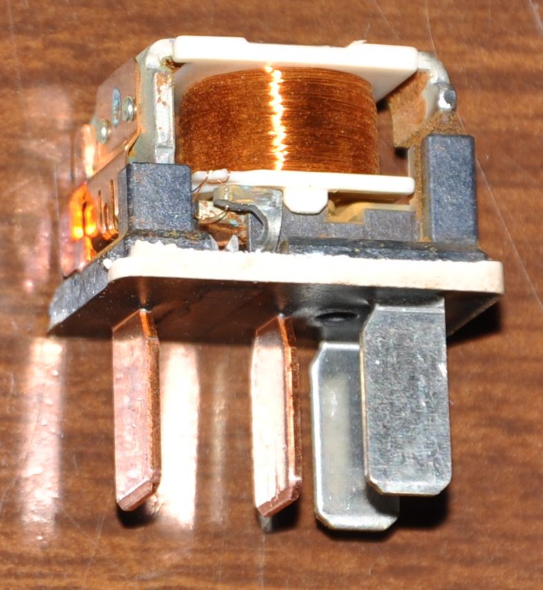
Silver legs energize the coil to magnetically operate the contacts. Put 12 volts across the 170 ohm coil (silver legs) and you should hear a "click". The copeper colored legs are suppose to close with low resistance. This relay clicked fine, but made no contact between the copper feet.
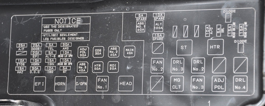
Fuse and relay map inside the lid of the fuse box. The relay we care about is labeled "MG CLT" for MaGnetic CLuTch.
.
.
.