How
To Repair
1989 Dodge B250 Ram Van Wagon 3/4-ton 8-cylinder 5.2L 318 in3
© 2010-2020
Brian Mork
Home
•
Site
Index
• Wiki
• Blog
Introduction
This web page contains a narrative log and
pictorial essay to maintain a 1989 Dodge B250 Ram
Van with 5.2L engine
with 153,000+ miles. At the bottom, I also have some simple
graphs aggregating lots of data on costs. This page is meant to
teach you, document technical data, and perhaps most of all motivate
and encourage you as you try to figure out your non-working Doge van.
I
included lots of links to web resources I found
useful. Chad's 1989
1-ton B350 van repair log
is also helpful. I have other pages about my 230,000
mile 1994 Suburu Legacy
with 2.2L. and 100,000 mile 2003
VW Jetta wagon 1.9L diesel. I always appreciate your link back to
this
page so Google
thinks what I say is important!
Before you start work on a car project that may take several weeks, consider
canceling insurance or doing "storage" insurance. My insurer used to
provide a "storage" option that provides only comprehensive
coverage and drops the cost of a newer vehicle from $52.50/mo down to
$5.00/mo. More recently, they've changed the definition of
"storage" to mean "state mandated minimum insurance," and for the Dodge
van in this article that change drops cost from from $27.17/mo
to
$6.70/mo. Or, if you can handle the risk, you could remove ALL coverage
including comprensive and save a boatload of money.
Bad Auto-Shutoff Device (ASD) Relay
Shift Lever
Catalytic Converter
O2 Sensor
Brake Cables
Battery
Brake Hydraulic Lines
Electronic Trailer
Brake Controller
Frame Hitch
Window Regulator
Fuel Pressure
Suspension Bumper
Air Conditioner
Compressor
Testimonies
1/14/2011 RN from Minneapolis,
MN wrote, "Thank You very much for
your informative article on
troubleshooting the Dodge B250 Van. I just experienced the same
situation with mine and thanks to your expertise I was able to do as
little as jiggle the wires around the relays and it started right up.
It was a LIFESAVER!"
1/19/2012 RS from mac.com wrote, "In
reference to your page on Dodge van exhaustive information ....
THANK YOU !!! Fantastic information ... great detail ... so much
appreciate! Very best regards ...."
4/11/2012 SS from Texas wrote, "I am
impressed! Gee, will you marry me!
For the sake of the baby, of course...(smile) Honestly, you
have obviously spent many, many hours on your Dodge van project. Thank
you so much for your time and energy, in both the labor you have spent
on the van, but moreover, the excellent record log you have provided!"
4/1/13 BR from Québec wrote, "The problem you
describe on internet that you finally solved was of great help for
me; I had a similar problem and your explanations solved it.
I talked to a mechanic and there was so many things possibly wrong,
that it would have cost me a fortune to leave it to a garage. I saw
your article on internet and followed what you have done or checked and
my problem is solved. Considering the age of my vehicule, it was a
matter of finding and fixing the problem or scrapping my Dodge
with 'only 122,000 miles' on it. My wife and I love it very
much. You saved our vehicule and our way of life."
11/21/14 RS from mymts.net wrote, "Found
the same thing on a van that was parked outside all summer, went to
move it in and no start. Checked fuses and then checked
internet, viola the relay was replaced prior and was hanging upside
down. Just wanted to say thank you for posting that blog."
8/27/16 NM from Canada wrote, "This
is great...thanks for the info....much better than ___."
12/4/18 AM writes, "...excellent blog and pictures.."
6/11/21 KB writes, "Amazing! Thank you for your hard work and
putting your knowledge out there for other Dodge owners to benefit!"
Spring 2009 - ASD Relay
The
first problem I worked on was doing a repair to the ignition. Early
spring 2009, my
1989 Dodge van with 135,000 miles was working fine, then one Sunday
morning, it sparked a
bit, almost started the engine, and quit. The engine turns over
fine - good and strong electrics, but it won't
produce
any spark, and won't run.
Click
on any picture to see a
close-up view.
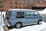
Our
van is affectionately known as "Big Blue". It's been across the nation
at least eight times and we hope it has a lot more life in it! Looks pretty nice even in
the cold snow.
We
have loved camping in it so far, and the rear seat comes out
for cargo hauling.
|
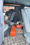
Tools are stacked up behind
me for easy access.
|
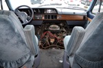
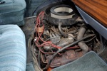
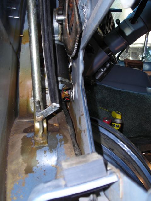
One convenience of the
full-size
Dodge vans of this era is that the engine is worked on from the inside
of the van. This is particularly nice during Michigan winters
when no
garage is available! Water on the floor is snow melt off my
boots.
|
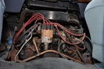
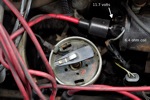
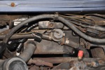
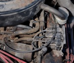
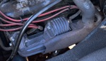
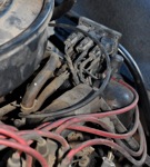
Ignition
parts up close. The distributor is beige with wires coming
out
the top. The coil is round and lays horizontally to the right. I pulled one of the spark
plugs going to the right in the picture, and could get no
spark.
Finally I pulled the central cable going *into* the
distributor and hooked it to a spark plug.
Nothing. Not good.
|
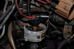
3/4 view of the ignition
coil and the spark plug I had out and was testing. You can see the
plug I pulled. Actually, it
looked
in pretty good condition. Looks like my valve gasket is
leaking a
bit of oil.
|
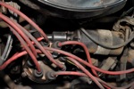
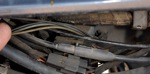
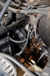
Coil and distributor. another
view of the coil assy. See the little grey wire?
There's one on the other side, too. They both
disappear into
the wire bundle, and I don't know where they go. Unscrewing
the
terminals is pretty easy and I did tests with wires removed and in
place.
|
Dropping
a bolt or screw down the throttle throat would be bad! To work on
the twin fuel injector harness, you
have
to remove the air filter and jostle the metal support aside.
|
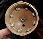
Inside
the distributor looked really clean for 135,000 miles. Must
not
be original. I picked up a spare spinner and magneto pick up from the
junk yard.
|
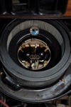
With
the distributor cap off, you can see the black disk in the bottom
(magneto pickup), and the spinner that puts spark out to each of the 8
cylinders.
|
Side
view. The distributor body looks a bit corroded, but
everything
inside was nice and clean. A little bit of pitting on the tip
of the spinning conductor.
|
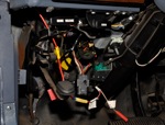
With
the lower dashboard panel removed, you can see the black box ASD relay
I was working on for 90% of this project. Uh.. turns out that
feeds only the custom interior lighting! It was the WRONG ASD !
|
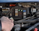
Having
exhausted every other possible problem, I dug into the "brains".
This the the computer ECU (Engine Control Unit) or PCM
(Powertrain Control Module) or SBEC (Single Board Engine Controller).
|
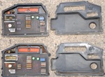
I
went to the local junk yard and pulled a ECU from a year (1988)
earlier 6-cylinder van. Would it work? I pulled the
air
cooling cover and compared them. Torx driver required to remove the
cover.
|
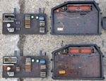
The
top plate or layer inside the computer is the higher power switching
transformers and voltage controllers (heat sinks) that use the white
connector. Underneath, the fully encased computer circuits
using
the red connector.
|
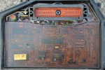
1989
8-cylinder. If you zoom in close, you can see the individual IC chip
numbers. Hey, I used to use these CPU chips in other projects
computer projects!
|
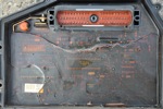
1988 6-cylinder. Only
significant difference I could see was one less air cover mounting
screw.
|
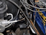
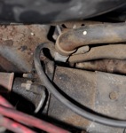
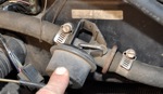
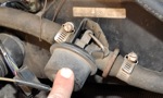
This
is what turned out to the be the real ASD (mounted on the firewall).
See the little grey box? That's the corroded ASD relay that
someone put into the harness. Water dripped down the harness
and
collected in the relay
|
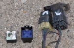
On the left: culprit and
cause. In the middle:
the interior custom-lighting switch relay found under the dashboard. On
the right:
two relays pulled from a 1989 model van. They seem identical
electrically, but have plastic molding that keys them into one
connector or the other.
|
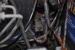
Original ASD ready to be
connected to the wiring harness. See how the relay body
itself makes a little water-proof hood?
|
The
ECU is connectd with three hex head bolts. Two were badly
corroded. One snapped off when it was removed. I
was going
to drill it out, but managed to untwist it with a pair of vice grips.
|
Original
8-cylinder ECU back into position. The 6-cylinder ECU was in
position when the van came back to life, so I know either can be used.
|
Thursday
(4 days into a repair job):
No
spark. I pulled a spark plug and held it up in the cabin area against
the engine block to see if a spark was visible. Nothing.
Fuses okay. Trying to figure out why there's no spark.
How can I check the coil? Where do the signals come
from
that go into the coil?
Friday
(5 days):
I
opened the distributor (pic r2c3,4,5) and played with the ignition coil
(pic r2c1). In picture r2c1, you can see
the
two terminals, with almost-red copper tips to the little bolt
ends. The two terminals are the primarly, and the large central
wire is the high-voltage output (compared to ground).
When
I removed the upper nut and grey wire, across the coil primaries
measured about 3.9 ohms (later tested to 1.6 ohms with a better meter).
I turned the keys on and the forward
and
lower nut was about 11.7 volts compared to ground.
Later, this was not reproducible and there was no voltage on
the coil anywhere. [later
note - I think the skittish voltage was because the shutoff relay
contacts were intermittent and failing with water corrosion.]
The upper
disconnected terminal was also 11.7 volts through the coil until I
connected the grey wire back on. The grey wire seems to
be holding the whole thing grounded because both terminals
then
moved to about 0 volts.
The
red wire secondary coming out of the coil center seemed loose so I
played with
it. It spun out easily, taking the center stem of the coil
with
it. I disconnected the two and screwed the coil stem
back in
firmly with a phillips screwdriver. While
the wire was off, I measured the wire alone and I think it was about
1.4 Kohm.
I remembered that these wires have built in resistance
to
cut down on ignition noise, so that seemed okay.
Chilton's
books specifies a maximum of 7 Kohm per foot. I clicked it
back
firmly onto the centerstem of the coil.
I
did the spark
plug test again by turning over the engine, and this time
got about 5 sparks,
then intermittent, then it quit doing any sparks while turning
over the engine. I
jostled
the wires around and my hold on the spark plug and tried again.
No
more sparks. Something is marginal, but mostly not working.
The voltage spike coming out
of the ignition coil primary is routed into the distributor, and then
it farms out the voltage to the right cylinder in sequence. After
pulling the distributor top, I couldn't
figure out how to remove the spinning stem from inside
the distributor to look deeper. A friend sent an incidental
description of how the distributor is suppose to work:
"Dwell
time is a term used to describe how long (degrees angle) the
points (mechanical) stayed closed. Mechanical points
stay
closed much of the time (shorted to ground). It is at the
moment
the points OPEN that the Spark actually occurrs. When the
points
OPEN, the field in the coil collapses and causes a high-voltage spark
in the secondary circuit of the coil, many thousands of volts, enough
to cause your spark-plug to spark. So........a coil is
basically
a step-up transformer you could say. The AC type current you
are
apparently seeing at the primary terminal on your coil while the engine
is rolling over is normal and to be expected. Actually, it
should
be AC current in that is vacillates from zero volts to around 12 volts
right? As you said, without an occilloscope, it would be
difficult to actually see this pattern with much accuracy using a
volt-meter.
Dwell time in a computer-controlled system is
greatly enhanced because the dwell can be increased thus providing more
field saturation time in the coil and the subsequent hotter
spark."
Saturday
(6 days):
I
pulled the coil off the engine and started testing things. Across
the
primary tests 1.6 ohms, which matches specs I found at Autozone. I
found 9.6
Kohm
from the secondary to either primary terminal. NAPA had no way
to
test this, but let me check one of their coils. Identical.
I think the coil is okay. I
don't have my oscilloscope out and running, so I can't see exactly
what happens, but the voltage settles into an AC signal across
the
coil primaries, so I think the ignition module is doing
something.
Safety alert! I let
the grounding lug for the coil mount float unconnected
and turned on the ignition. When I did this, the
fuel injectors went full bore ON and
started spraying lots
of
gas down the throttle valves (pic r2c2).
I
couldn't tell what the gushing sound was, and then saw it! Don't
do testing with the ground wire lug of the ignition coil disconnected
or you're sure to
flood the engine or start a fire. This is still a bit
confusing. With the ASD energized, the "Z1" wire should be at 12
volts. Maybe the diagram below is simplified too much and the
ignition coil provides a DC ground keeps the fule injectors off, and
then I let it float up to the 12 volts?
Autozone
was willing to test the ignition module transistor, but I can't find it
yet. I've looked all over on the firewall. It's just
not
that complicated, and I can't find it. There is a
big bundle
of wires going into a plastic shroud covered item about 6-8
inches
across about in horizontal center of the firewall. I think
it's
the computer module. I'm fearful that the
ignition module
is buried in the bundle somewhere, or part of the computer module.
[later note - yup, the transistor is
in the ignition moduel on this van; that's why I couldn't find it.]
I read
on on the
internet, a post about control modules from years prior:
"I
have the same year and make of pickup [truck]. The problem is
in 1988 depending
on how early or how late in the year it was produced it could have 2
different ignition systems. If its a late model like mine it
wont
have an ignition module. Late models ran a hall effects pick
up in
the distributor. Which just relays a signal to the computer
and
tells it when to ground the coil to send spark to the
distributor. But on the early models it should be on the fire wall or
the drivers
side fender well. good luck hope this helps you."
This matches my observation in
my 1989 model that there is no separate ignition transistor
module. It's embedded in the computer module.
Monday
(1 week 1 day):
I found out how
to do Chevrolet
1980s-1990s computer service codes (more authoritatively
listed on the Mopar computer spec sheet, linked below).
Basically,
within 5 seconds, turn the ignition power on-off-on-off-on, and then
wait and count blinks. I was getting codes 12, 42, and 55.
12 is a generic "battery has been disconnected" code that
seems to always show up. 55 is a "end of message" code.
42 is meaningful, and can have several similar
interpretations as listed on Alpar's web page and the Chilton manual:
-
42 Automatic shutdown relay circuit open or shorted, OR
-
42 Fuel pump relay control circuit, OR
-
42 Z1 voltage missing when autoshutdown circuit
energized
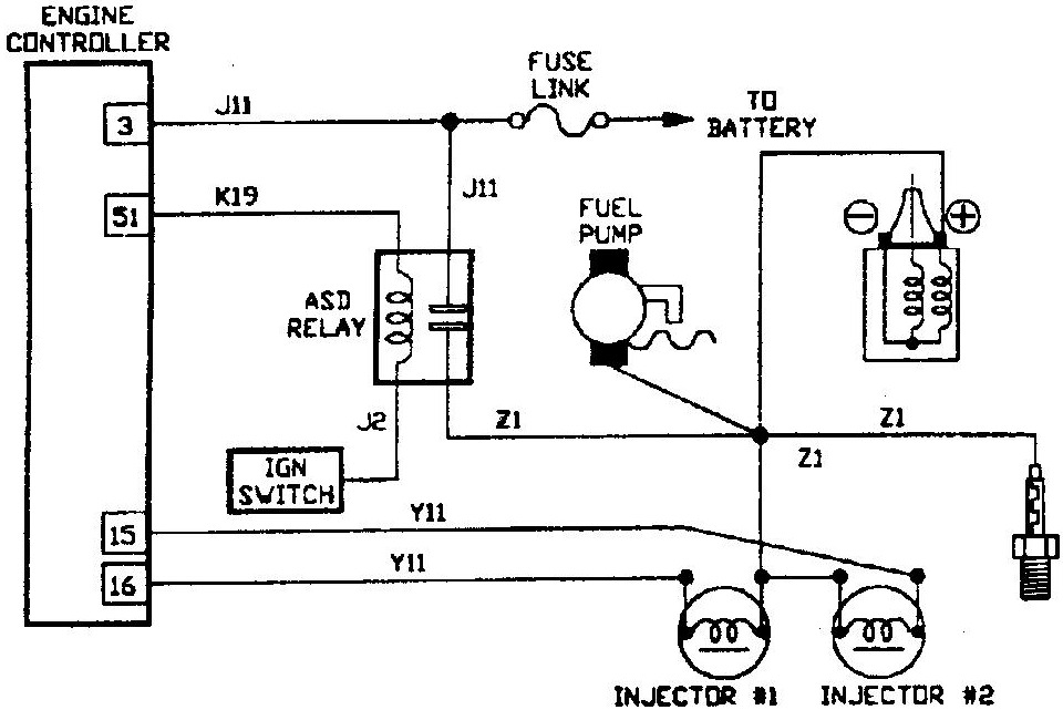
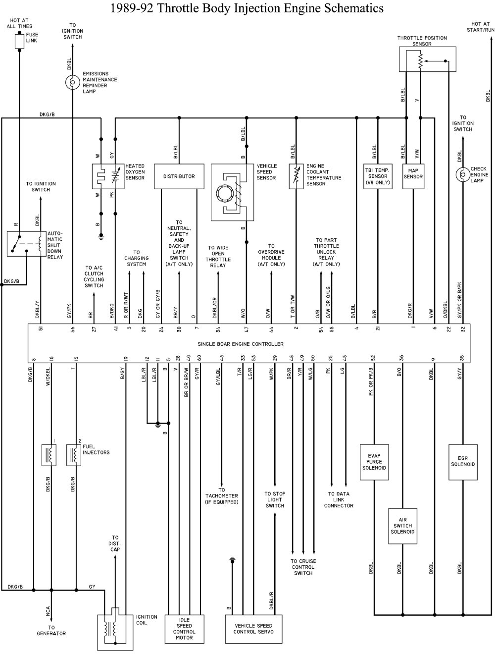
The Z1 voltage is the voltage of the circuits fed by the
autoshutdown relay, shown in the Chilton's
schematic diagram. This
includes fuel pump and
switched-battery feed to the ignition coil(s). The Z1
circuit leaves the Auto Shutdown Relay and splits into two paths: the
fuel
pump and the positive side of the ignition coil. The ASD relay (and,
therefore,
the Z1 circuit) also feeds the fuel injector(s) driver(s).
I don't
think I have any trouble with the fuel pump.
In fact, as mentioned above, the fuel sprayed out under pressure
when I disconnected the
high-voltage spark coil from grounding mount screw.
To check
these codes, I
unconnected the negative battery terminal while charging the
battery from another car. I unscrewed the computer covers and
took some pictures for about 1/2 hour and then hooked up the negative
side
cable and read the codes without trying to start first. I
received 12 and 55 (no 42). Then I tried to start and it
happily cranked over and over with plenty of power, but did not fire
once. Checking codes, I am now again receiving code 42.
The local
Chevrolet dealer
says they have no more 1989 manuals, and so
he can't advise where the ASD relay is at. He said it should
be stamped with the number "52-33-302" and costs about $28 to buy a new
one. I found two relay-box looking things bolted to the
firewall.
One to the immediate side of the main computer box toward the
driver side. The second is down by the driver's right foot.
One has an obviously different number; the second has no
discernable number. [later note - the
one on the firewall by the driver's foot was the ASD relay, but I
didn't recognize it at the time.]
Tuesday
(1 week 2 days):
I
found the ASD Relay. It's a black box in the wire bundle up
under
the dash, outboard side of driver's left leg. [Caution
- read
this entire article! I initially found an ASD relay that had been wired
inside the cabin for the custom interior lights. It has nothing
to do with the
ignition, which is why I started getting unexplainable behavior
thinking it was the ignition ASD relay.]
Mine
has a part
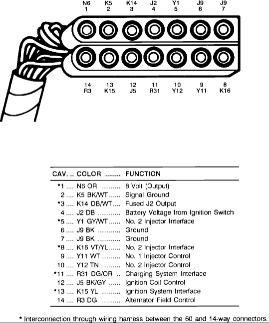
stamped "46385" and inked "4273307 0179". Lots of electrical
testing today. I found an ASD
relay electrical mechanical pinout diagram
at dodgeram.org. Basically apply 12 volts across the side
terminals activates the relay, and the up/down terminals are the
contacts. Normally-Open on the
top. Normally-Closed on the middle. Common on the bottom.
The four terminals are
numbered 30, 85, 86,
and
87. Looking at the male pins of the relay, pin 30 is on the
bottom and pin 87 is on the top. Pin 85 is on the right, and
86
on the left. Looking at the female connector for the relay,
pin
30 is on the bottom, and pin 87 is on the top. Pin 85 is on
the
left and pin 86 is ont he right. A textual
description of ASD relay pinout is available at
justanswers.com. I posting by "dsramprat" at
automotiveforums.com gives a checkout
procedure for the ASD relay.
- Pin
30 - pink/red wire - bottom of relay receptacle or cavity. Car always
provides
+12v even when there's no key in the car. This is confirmed
to be
connected on the rear or bottom side of Fuse 6 in the glove compartment
(0.7 ohms with fuse removed). It also goes to Pin 3 of the
ECU
according to Chilton's. This voltage drops to about 9.75 v when
cranking the engine ... yea my battery is getting weak after all this
testing.
- Pin 87A - middle pin on my relay is clipped
off,
the outer
pin is intact.
- Pin
87 - brown wire - top of the relay cavity connectory. This
is the relay output. Power from Pin 30 is switched to this
pin
when the relay is energized. Feeds the "Z1" circuit that
includes
fuel injectors, ignition coil, and probably oxygen sensor heaters, and
generator (alternator) field.
- Pin
86 -
white wire - +12 v from the car when the ignition switch is on.
Other
sources
indicate it is fed through Fuse 9, but that appears to be not true with
my vehicle.
- Pin
85 - black - I believe the ECU grounds this in order to switch the ASD
relay on, probably by pulling the collector of a transistor toward
ground. Resistance between pins 85 and 86 is about 82 ohms,
implying 12/82 or abou 146 milliamps draw when powered. That
would not be too much for a transistor.
Okay..
that's all great. Relay appears to work out of the van.
In the van, things get wierd. [later
note - Remember, this was the incorrect interior ASD relay that I
found; I was basically testing the interior custom lighting circuits,
which is irrelevant and confusing.]
White
wire ignition +v on the hot side of the relay coil stays at constant
+12v when
ignition is on and not cranking the engine. It drops to about
1v
within a second when cranking, and then returns to 12v as soon as
cranking stops. Chilton claims this is direct from the battery through
a fuse link. Another web page says fuse 9, but that did not
check
out on my van.
Brown
wire relay output goes to +12v when the ignition is turned on.
It drops to 0 v when cranking and returns to 12v when
cranking
stops. This is true with or without the (-) side of the
ignition
coil connected. This is an important distinction because
theoretically 12v / 1.6 ohms or 7.5 amps of current goes through the
coil, and this could draw down a voltage.
Resistance
checks indicate the (+) side of the coil does not appear to be
connected to the brown wire pin 87 ASD relay output as shown in
Chiltons. So I'm not sure the simple circuit diagram is
complete. [later note - I was testing the wrong relay; the output was
literally connected to nothing]
The
hot side of the coil primary behaves differently, too. With
the
negative side disconnected (no load), it sits at 12v with the ignition
on, and drops to about 4v when cranking. Remember, this is
without current flowing through the coil. With the (-) side of the coil
connected, the hot side is never above 1 volt DC. I don't
have an
oscilloscope to watch the fast time behavior, so it might be pulsing up
to 12v as it should, but I can't be sure.
When the
coil hot
side is at 12v, the relay output is also at 12v. In order to
be
sure I wasn't reversing the relay connectors, I floated the entire
meter and just monitored voltage across the relay coil (pins 85 to 86).
It was 12v when the ignition was on, and dropped to 0v within
a
second of cranking the engine. Based on this, the relay is initially
energized, and then is NOT energized as soon as cranking starts.
Output voltage is 12v when the ignition is on, and
drops to 0v within a second of
cranking the engine.
Wednesday
(1 week 3 days):
With
the relay hooked up in place in the van, I hooked up 4 jumper cables to
monitor voltages [later note -
remember, this entire day of testing was with the wrong relay].
The relay coil measures 80-65 ohms,
depending
on how long I let the voltage die away after having the ignition on.
It stabilizes long term at about 65 ohms, which is okay since
there are other circuits in parallel.
Relay
primary
With
the voltmeter floated across the relay coil primary circuit, it is
13.7v with ignition on (coil is energized). When cranking, it drops to
about 0 volts across the coil, and rebounds to 13.4 v after cranking. I
can also feel the relay click on, with ignition, then off when
cranking, and on again when cranking stops.
Interpretation -
during cranking, the ECU releases the grounding on Pin 85 allowing both
sides to rise up to +V, or the ignition +V drops down to ~0 v to match
what the ECU is commanding. Is
ECU releasing, or switched
ignition +V is dropping? [later
note - actually, the pin
86 +v ignition voltage was dropping away because the *real* ASD relay
was being turned off by the computer almost as soon as it turned on -
which is what it's suppose to do whenever the computer sensed the
crankshaft of the engine was not rotating]
Relay
contacts
The
hot side of the relay contacts stays at permanent +V no matter if the
key is in the car, or ignition is on, or off, or if cranking or not. Connecting
the voltmeter across the relay contacts, shows that the voltage across
the relay always hovers about 0 volts, bouncing around a little bit.
That's strange since I would expect the output to not hang around +V
when the relay is open.
Output of relay contact
compared
to ground is ~ 0v when the car is off, +V when the ignition is on
(should be since relay is closed), and t hen ~0 v when cranking.
Strangley, across
the relay contacts always hover about 0 volts, cranking or not.
Since
Pin 30 is confirmed fuse 6 +V, this means the output side of the relay
must float up to about +V even when the relay is not closed. [later note - the output
was a
floating wire connected to nothing; voltage reading was meaningless and
I should have noticed that by the floating around behavior.
Using an
oscilloscope would have shown random voltages on the unconnected wire.]
Checking
the relay out of the car, with the car battery across the coil, gives a
solid click and release. Resistance goes from infinite down
to
less than an ohm. Interpretation? Relay is fine.
Summarizing
three states:
- Power
off the van - Supply side of contact (pin 30)
is at +V.
- Ignition
on - Coil hot side pin 86 is at +V, ECU is grounding pin 85,
energizing the relay. Supply side of contact is at +V, and
relay
output pin 87 is +V.
- Cranking
- 0 volts across relay coil, indicating relay is commanded
de-energized. No voltage output at pin 87 output but it also
seems to float up to +V when a floating measurement is made; this is
true even with fuel injectors and ignition coil disconnected (no load).
Also output shows no AC signal, and no conductivity to ground
with power off.
|
power off |
ignition on |
cranking |
Description |
pin 86 relaly coil -
ignition
+V power available
|
0 |
12v |
1v |
This is capable
of sparking and heating small jumper cables - be careful what you let
this touch, especially pin 85! |
| pin 85 relay coil - ECU
grounding relay energize |
not measured |
not measured |
not measured |
I don't know,
but I'm betting there is a transistor inside the ECU with a transistor
collector terminal pulling this to ground when appropriate. |
| across 85-86
coil |
0 |
13.5 v |
0 v. |
ECU commands
relay closed with ignition. Commands open when cranking. |
| pin 30 contacts
input |
12v |
12 v |
10 v. |
Slight loading,
but otherwise stable power. |
pin 87 contacts
output (suppose to be switched 12 v)
|
0 |
12 v |
~0 |
Feeds
downstream circuits with +12v power when the ignition is turned on. |
| across 30-87 |
0 |
~0 |
~0 |
Consistently measured ~0
volts [later found output wire was floating unconnected to anything] |
Other
observations. Maybe a tan wire from pin 87 output goes to fuel
injector? Checked with ohmeter. No. Fuel
injectors
have about 3 ohm across coil. Top two pins and bottom two
pins of
4-pin connector.
Why does ECU command ASD relay open when
cranking? OR, why does switched ignition power die?
Is this
about the crank case indicator not giving a pulse when trying to start?
Chilton manual shows crank reference signal error diagnostic
codes for years 1996-1998, but nothing for 1993-1995 vans, and nothing
about crank signal for 1989-1992 vans (mine).
Check this and confirm crank sensor is giving a good signal.
Otherwise ECU cuts out the ASD relay.
Saturday
(1 week 6 days):
Salvage
yard shopping trip with a friend (thanks Kevin!). I came home
with replacement computer,
replacement
distributor wires, replacement oxygen sensor, replacement
fuel injectors. I should have grabbed the coil, too. In
case your local salvage yard does not have the appropriate vehicle, you
can also purchase new SMEC computers
from Mopar.
Looks like my 8-cylinder 5.2L 3-speed vehicle uses part R4379887,
4-speed uses R4379889 for FEDeral state-side vans. (Okay, side
question: If I have 3 spd plus and O/D overdrive switch, does
that mean mine is a 4-speed?) The one I actually found at the
junk yard came from a 1988. I'm not an engine expert, but
considering it had a 6-cylinder, it must have been a 3.9L LA V6.
That would be SMEC or SBEC part R4379929 for FEDeral or CANadian
vehicles. Direct replacements are available on the web from autopartswarehouse.com
or other distributors for about $170.

Sunday
(2 weeks):
Replacement
computer didn't change anything. Relay output still stays
high
with ignition, drops low during cranking. Error code 42.
Monday
(2 weeks 1 day):
ASD
relay under the dash still works fine. Actually, I found
another
relay forward of the firewall on the end of a dangling wire bundle that
has the same electrical connection
with the middle pin 87A (NC Normally Open) tab in place. Not
sure what this relay is for, but regardless of the part number, it
looks like it could be used for an ASD relay. [later note - boy was I dense! My
brain still didn't recognize this as the real ASD ignition relay!]
Is there a ballast resistor circuit that needs attention?
Actually, it would be the parallel
circuit that needs attention. The ballast resistor circuit is
used when the car is not cranking. It provides power to (or
indirectly to) the ignition coil. This is to limit the
current
flow so the ignition coil doesn't burn up. However, when
cranking, the starter pulls the battery so low, that the ignition coil
needs direct power on the (+) side. If the parallel non-ballast
resistor circuit is open, then I would get the behavior I am
experiencing.
Rooting around, I see two wires on the starter,
one big and one little. Follow them up, and I find the little
one
is a brown wire that goes to a connector, joined with a little red wire
direct from the battery. Other side of the connector is a brown and
pink wire, just like the the two colors on the ASD relay.
Maybe?
No... no continuity.
However, I did find two wires
under the dashboard labeled "ignition +v" and "battery +v" with single
wire connectors.
Looks like you can plug one or the other into the red wire
(and
20 A in-line fuse). Turns out this is what feeds all the
interior
lights for the custom van. At least I've learned something
today!
The
brown and pink wire disappear into a wiring bundle, and from there I
have no clue where they go. How exactly does one "trace the
circuit" without knowledge of where it's suppose to go?
I need a working van to start making comparisons to. Or, I'm
about ready to assume
it's a fault on the ignition of the ASD relay that is dropping the ASD
relay, and hotwire
+12v onto the Z1
circuit relay output and hope that nothing blows up.
At
this point, thank you to
friend Neil who sent an email summarizing with essentially this
thought: "When it really starts looking complicated, it's amazing how
often it really is a simple thing that has been overlooked." How Prophetic.
I couldn't sit still and do computer work. I went outside and
after confirming things were still responding as previously, I turned
on the ignition. ASD relay output was +12v. Then I
cranked the engine and ASD relay output dropped to no voltage. Then I
did something differently, while monitoring the current flow with a 10
AMP meter, I
hooked a jumper wire across the relay so that it didn't matter what the
relay was doing. I decided to force +12v onto the Z1
circuitry while cranking the engine. Initially a
quick tap to see if there would be a spark. Nothing.
Longer, and feel for heat in the jumper wire.
Nothing. Nothing on the meter.
No change. No current draw. Switched down
to a 300 milliamp fused scale on my meter. Still nothing!
There was NOTHING taking current through the relay.
This confused me enough that suddenly
realized I had never determined
where the relay output went to. I needed to know. Because if
it fed the ignition coil, there is NO REASON for the ignition coil to
be at zero volts if I was shorting +12v to it. Instead, if
there was a short or something, then the whole ignition coil should
have burned up. Something wasn't right.
Short story? After tearing into the dash, I found the ASD
relay I found fed the wire labeled "ignition +v" wire I had found
earlier in the day. Since my custom interior lights were
hooked to another "battery +v" line (so I can run lights while camping
with
the engine off), there was literally nothing hooked to the output of
the relay. Uhh... very clearly, the ASD relay I had found and
been diddling with for a week was not the ASD relay and it's output
wasn't even being used!
Now that I knew what an ASD relay looked at, I went back with vengeance
to find it. Turns out tucked up next to the brake system on
the firewall, there was a little box hooked to nothing, hanging on a
metal bracket. Dangling near the bracket was a terminated
wire bundle, but when I looked closely, it was not terminated with tape
and a plastic plug like other terminate wire bundles. There
was a little plastic box connected to it. I unplugged in and
VIOLA!! the plugs looked and were labelled exactly like an
ASD relay.
I poked and prodded with my ohmeter and found that this was a
relay, and it clicked fine with voltage on it, but the normally open
contacts dropped to only about 4 Mohm resistance when closed.
The connector look copper blue and corroded. I
think dangling down in the engine compartment made this a perfect water
run-off connection and water got inside the relay and corroded the
contacts.
I took the inside ASD relay from the interior light circuitry and
jumper cabled it into position because it physically would not fit onto
the cable connector. Measured volts and everything looked
good. I cranked the engine, and within 1.5 seconds, the old
Chevy 318 came to life! Boy was it good to watch the fuel
injectors popping fuel into the throttle body. It was still
running on the junk-yard 6-cylinder computer.
I ran to the junk yard with my toolkit and pulled two ASD relays from
a similar van - a 1990 Dodge full-size van with the
same engine. I
also grabbed two headlights. From the 1988 Doge Ram
Van with the smaller 3.9 L engine mentioned earlier, I took a few spark plug wires, and
the ignition coil. $10. I almost got the air
conditioning compressor out to replace my broken one but one bolt was
rusted up badly. I need my long arm socket. I guess
that's for another day...
Tuesday
(2 weeks 1 day):
Now that my eyes
were
familar with what to look for, one of the little boxes bolted
to the firewall
started looking like a relay. And... the wiring harness I
found would perfectly reach it. I unbolted the firewall
device, and looking at the bottom.. sure enough it was an ASD relay. I tested it with
my meters and it behaved perfectly.
Instead of using one of my new relays, I plugged the wiring harness
into the relay that had been bolted unused to the firewall the entire
time. Result? The van ran beatifully!
I pulled out the 6-cylinder 1988 ECU and repaired the one stripped
mounting bolt hole. I put my original ECU back into the van.
I taped up wiring bundles, tucking some behind the battery away from
water dripping, and plugged the ASD harness into the firewall mounted
ASD relay that had been there all along.
Summary? Someone had unconnected the harness from the factory
ASD, plugged in another one, and let it dangle in the water.
I have no idea why
someone
would have plugged a dangling ASD relay into the wire bundle harness
and left a
perfectly good relay bolted in position to the firewall. I fixed the van by plugging the
harness back into the factory
mounted relay and discarding the water damaged relay. What a trip to
get to this simple answer!
Epilogue:
Hopefully our "Big Blue"
van has a few more trips in him. We're anxious to spend a
night out at the soaring club field now that Spring is coming
on. I
now have a small plastic storage bin under the back seat.
Spare injectors. Spare fuses. Spare coil. Spare
relays. I should go pull the distributor sensing coil from the
salvage yard van, maybe
the entire distributor stem going into the engine.
May 2009 - Shift Lever:
Three months later, and several
thousand miles later, the van unexpectedly won't start again!
This time, it wouldn't turn over even though all electrics look
strong. Again my friend Neil's words echoed in my head, ""When it really starts looking
complicated, it's amazing how
often it really is a simple thing that has been overlooked." Uh... yea.. check that the shift
lever is settled
into the Park
detent! On an older van, after the cables have stretched, this
may not perfectly match the dashboard indication. With the
transmission secured into Park, the van started with no problem.
Everything is not a difficult problem. It's okay to look for the
simple, first.
May 2010:
Fifteen months after the starter relay fix, Big Blue
successfully made another cross-the-nation road trip. Working
fine. No other repairs yet. ...still ticking after 22 years.
October 2010:
One more round trip across the
nation, for a total of 5 one-way trips so far. Keeps on ticking!
June 2011 - Catalytic Converter:
Stuck in the office too much,
and not enjoying the outdoors enough, and doing huge job commute
distances, I haven't driven the van for a
while. I took it out to drive it around the block. It was
hesitating and had no power, even under no load.
Pressing the gas
pedal all the way down accomplished almost nothing. The catalytic
convertor was making strange rattling noises, and in fact, the van was
behaving as if a potato was in the tail pipe. Took it to have the
catalytic converter replaced, and yes.. it was all destroyed
inside. $198.75
including parts and labor.
But the lack of acceleration is still there. Looks like more
work. Timing chain slipped? Distributor shaft is loose in it's
bushing? Timing adjustment (distributor body) came loose? It runs
fine to start and idle, so I don't think it's a timing issue. Weak
spark so that it can't do high RPMs?
Research about loss of power and no acceleration on the web at about.com.
No fix immediately apparent.
November 2011 - O2 Sensor:
I was pre-occupied most of the
summer with some contract work requiring a l-o-n-g commute. I
didn't have a chance to test the van more until now. I pulled
computer codes and it reported an O2 sensor stuck at full
rich.
After about 2 hours mucking around trying to get the sensor out from
it's rusty threads, I decided to give up, and took the van to the
commerical repair shop to replace the sensor. Or so, I thought...
They rang up a day later and
reported that the van needed $1600.00
repairs. Uh.. this I needed to see. A visit to the shop the
next morning whittled down the work to about 1/3 of that. After it was
repaired, I received Big Blue back from the repair
shop. It had been
showing zero to no acceleration, chugging, pausing, no power, every
time I pulled away from a stop sign. All I could tell was the
computer was complaining about an O2 sensor stuck on
full-rich.
What came of the visit?
New front shocks. New
passenger-side exhaust manifold.
New valve cover gaskets. Not
exactly
related to the original problem, but the original problem became CND
(Could Not
Duplicate) at their shop, so they couldn't do much with it. Price tag
for the named repairs was $511 plus $78 mail order for the new exhaust
manifold. Big Blue balked and choked and
stalled twice on the way home, but that was during a wet and rainy
morning. For several days afterwards, the van has run well.
However, all the dashboard vents would no longer blow air out. It
wasn't this way when it went into the shop. See the narrative
underneath the first picture to understand what happened.
Viewed
from the passenger seat, this is the vacuum adapter mounted into the
intake manifold. It has several hoses connected. The little
vacuum hose hooked on the left side was unbelievably slid over one of
the spring clamp arms rather than the vacuum connector! I
corrected this and now the dashboard vents work again.
|
This
is the vacuum distribution center. Electrical control comes in
from the top left of each switch. Vacuum lines come out the
bottom and go various places.
|
Picture
of the new exhaust manifold. The old one had a rare perfectly
working riser valve (chokes off exhaust if the engine isn't warm which
worked like a spring bi-metal thermometer). The new manifold has
a
port plug where the riser used to be. Two aft bolts were missing
for the last 20,000 miles, and it was time to fix the problem.
Expensive 2.8 hours of labor to drill out most of the bolts, which were
rusted and snapped.
|
Heat
and A/C vacuum lines. The top one comes from the vacuum adapter
on the intake manifold (first picture). Based on what you select
with the control, vacuum is routed out one of the other tubes.
|
Example vacuum
control, visible top center underneath the open hood. This is
with the A/C selected ON.
|
Example vacuum control, visible at
the top
center underneath the hood. This is with the A/C selected
OFF.
|
Another picture of the vaccum
distribution center, back passenger side of the engine. Not sure why I
took two pictures of this.
|
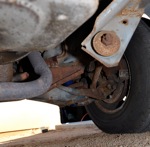
Looking
into the engine compartment on the driver side, you can see the
stainless steel line coming up from the catalytic converter.
|
Oil
was still oozing out of the driver side valve cover gasket and caused
asphixiating smoke when it dripped onto the hot exhaust manifold.
This picture is from under the car, looking up to see the bottom of the
manifold where the oil collected.
|
New blue shock on the driver side,
looking from behind.
|
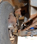
Passenger side front suspension,
looking from underneath the van.
|
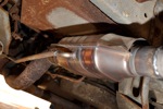
New
catalytic converter. The other one had ceramic honeycomb broken
and shattered into dozens of pieces. Notice the tube coming off the
side, which is routed up into the vacuum system.
|
Driver
controls for environmental controls. The little vacuum lines come
in and connect on the bottom back left side of this picture.
Photography flash was not positioned right, so you can't really see
them, but that's where they're at!
|
August 2012 - Brake Cables:
The van is running fine, but
with a planned trip to the moutains, it was time to replace the rusted
tight rear brake cables.
I purchased to new rear
cables
from Rock Auto. Price to
have both cables delivered was just under $20.
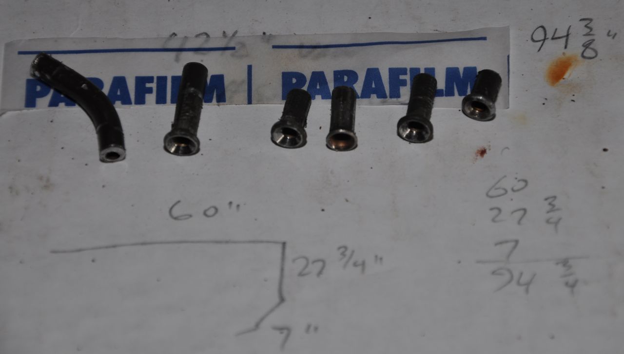
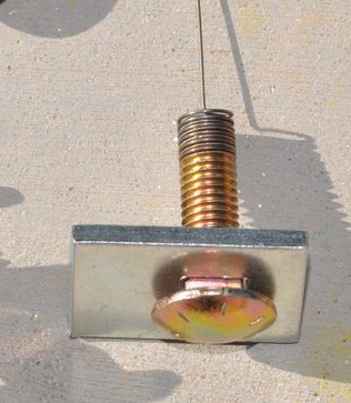
The
old left rear brake cable had 43" from crimp to crimp. The new
one came in a bit long, and I suspect it's 44-1/8" long. The new
left brake cable is on the right side of this rearward looking picture. |
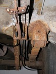
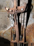
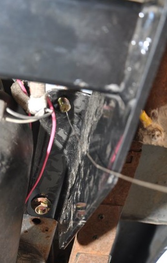
Closeup
of where the front parking brake cable (top of picture) connects to the
two rear brake drum cables. Notice the clips to hold the cable
sheathing in place are not yet in place (between the rubber sheaths and
the metal mount flange). |
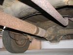
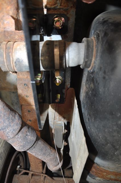
You can see the right rear
cable
extend over the exhaust pip and over the drive axle. The bolt |
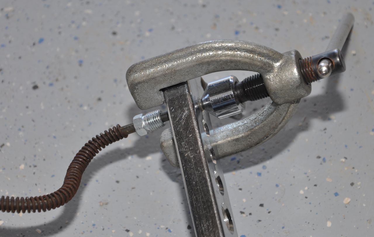
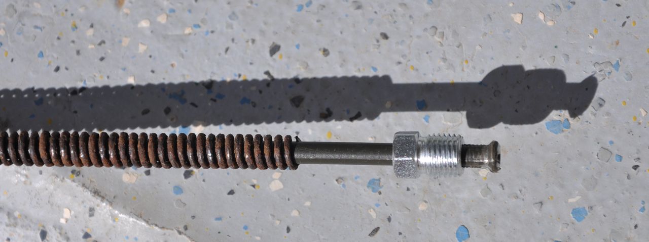
Removing the old cables had only one significant problem. The
end of the cable from the front of the van terminates in a long
threaded bolt with an adjustable nut. That nut was rusted solid
onto the cable end, and I could not grab the bolted end enough to
rotate the nut off. I used a lot of WD-40, and two vice grips on
the bolt, but still no rotation. I ended up torching the nut with
my propane torch for about a minute and then after letting it cool,
held the bolt with two vicegrips, and the nut with a non-ratcheting
socket. The heat/shrink cycle of the metal was enough to crack
the rust loose. Wiggling back and forth and more WD-40 finally
got the nut to let loose.
During installation, two modifications were made. The new cables
did not have the
expando-rubber sheaths that prevent water from blowing into the
cables. I slide the old ones off the old cables and installed
them onto the new cables. Also, when installed, the cables came
up about 1" different in length. Either one was too short, or one
was too long. I considered cutting the longer
new cable and crimping on my own end piece. I took a more
reversible path. I hack-sawed off an old crimp
with about 4" pig tail, and used two cable clamps to use the pigtail to
extend the new right side cable.
I still don't know for sure which cable is incorrect. Suggestion
for you: remove your old cables and actually measure them before
cutting them up! After finding the length mismatch, I layed out
my short left side cable and measured 43" between the crimps.
Rock Auto's parts catalogue refers to 44-1/8" length several places, so
I'm thinking my van must have had some shorter version cable installed
years back.
BTW, these brake cables are almost sure to lock up or rust up.
The NEW right side cable is so long, it has tons of friction in
it. I will make sure to use the parking brake every time now,
just to make it practice wiggling in the cable sheath. Dry desert
air also will tend to help. I dribbled some oil into the short
cable, but I'm not sure it will help. I didn't get around to
oiling the long cable before it needed to be installed to make a
departure schedule.
September 2014 - Battery:
After sitting in the garage for
several months, the old battery
(7 years ago) just wouldn't take a charge any more. I purchased a
new one at Walmart. Their cross reference provided a battery type
that was all sold out. The battery tech walked by and said, "Uh..
you have an old Dodge van, right? That's the wrong number anyhow
- it's too tall and skinny. Buy this one. You can get the 3
yr warrantee for $86, or the 5 year warantee battery for
$94." And so I did. Van is back to starting right
away when I turn the key.
Now I need to go work on the pesky air conditioner compressor, which
locked up a while ago. I have a new one purchased but just
haven't had the time to install it yet.
Top of the van paint is peeling due to baking in the hot desert
sun. Looks like it's time to paint the van, too.
January 2015 - Brake Hydraulic Lines:
I started crawling around under
the van to route wires for an electronic brake controller. The
brake line going into the rear axle divider looked a bit rusty and the
more I thought about, I had no desire to loose my rear brakes while
pulling a trailer around. I decided to replace the brake line.
If you're doing brake lines, you have to obtain a set of "line
wrenches" - they're like closed box end wrenches with a slot cut in
them to slide over a brake line and then turn the coupling
nut. In this case, Harbor Freight is not the way to go
because theirs have a receeding edge design. It's easier to slip
over a nut, but doesn't grab as much of the nut - and you need all the
surface area grab you can get because these nuts are almost guaranteed
to be rusted badly. This turned into a problem for me.
The front of the brake line connection was along the front left side of
the van. After
unclipping the brake line from
the van body, the front connector nut actually came loose easily and
leaked a
little fluid. I retightened it until I could get the rear coupler
loose.
The rear connector was
directly screwed into the flexible hose that
fed the back axle divider. What a rusted nightmare. My
brain was thinking the
nut was like the back of a refridgerator ice maker tubing line, where
the nut screws over the
threads. Not true. For brake line
fittings, the nut slides into
the threaded receptable and pinches the
double-flared end into the coupler. I could not get it loose
until I remounted the hose back into the van frame holder (which had a
hex shaped hole and kept it from rotating). Finally the nut let
loose. I rotated it a few times but the rusty line just in front
of it tore open. I had not loosened the nut, I had torqued the entire
metal brake line until it split.
Turns out moisture gets down between the brake line and the brake line
nut and rusts the nuts up tight. You can expect that the brake
line will twist off or break off or you'll have to cut it
off. However, save the pieces because you'll need them to
get the right length.
You can measure a brake line with twists and turns using a roll of
solder, holding them side by side. However, because I had a
double flare tool, I was able to buy a 25' of bulk 3/16"
brake
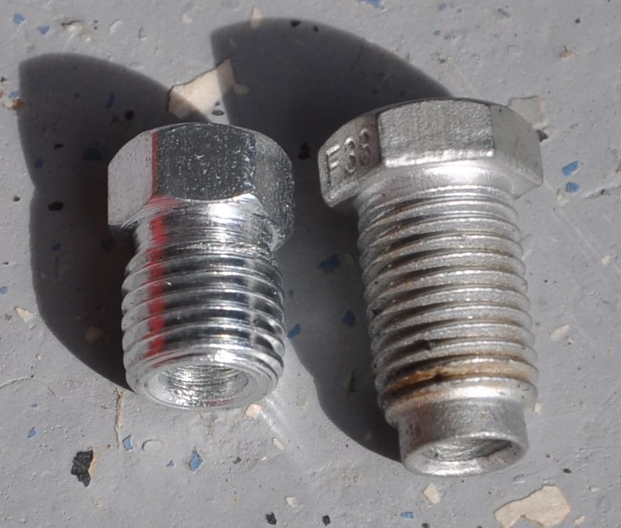
line for $21.27. Buying the nuts was a pain. They're only
$2.89 for 5 of them, but do you know that 3/8" and 10 mm are
nearly indistinguishable?! The threads are either 24 tpi or 1/mm,
which is 25.4 tpi - also indistinguishable. Only by looking up
the hose fitting did the
guy at Autozone figure out it must be the SAE size. That was
strange to me because I needed to borrow a friends 9 mm line wrench
when my 3/8" line wrench didn't fit. I think someone during the
last fix accidently put in a metric nut.
Next problem - unless you know otherwise, buy the nuts that have thread
run all the way down to the end. Otherwise, installing the brake
line won't engage enough threads to make a good connection. I
know this because I totally build a new brake line and then had to cut
all the ends off and swap out brake line nuts when the first nut didn't
reach deep enough into the fitting to grab any threads in the coupler.
Use a tubing bender to get the brake line about right. Then use a
plier to wiggle and loose the rusted spring surrounding the old brake
line and install it onto the new brake line so that it does not chafe
against other metal things. I ended up using an abrasive cutoff
wheel to cut the spring into several sections so it would slide on
easier.
Slide the nuts on the ends and create the double-flared ends.
Then fit and test fit over and over again unti the ends nestle into the
couplers straight and snug without the nut. Only then, gently
spin the nut down over the line into the coupler.
I started bleeding the brakes and the left side worked great.
On the right side, the bleeder valve broke off. There was no
way I could recover the nub, so I had to go buy another wheel cylinder
(the brake hydraulic actuator for drum brakes). Fortunately the
new
one costs only
cost $11. However (!!) this means I had to now pull the brake
line going into the old wheel cylinder. Suffice it to say that it
too was very rusted. I used a torch to heat the nut and it came
loose, but when turning the nut off, it was still rusted to the tubing
and so eventually the tubing torqued off. Now I had to replace a
second brake line.
Turns out the rear axle brake line divider is bolted down to the rear
axle with an incidental axle vent bolt. It backed out easily
after pulling off the connecting breather tube. With the brake
line
divider loose, I was able to grab it with a big crescent wrench and
torque the brake line nut free from the brass fitting. After
another morning of re-making this second brake line from scratch it was
back in
place. It was much shorter, but the angles and bends were much
more compact.
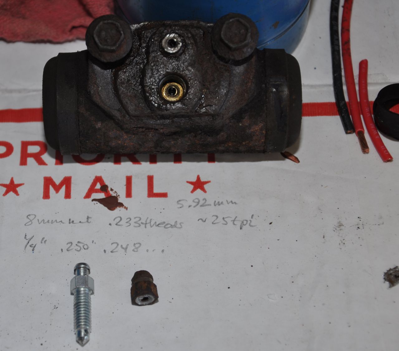
Caution to self: for
some reason, instead of SAE sizes, the new wheel cylinder has 6 mm
threads and requires a 7 mm nut on the hex part. I wish the
manufacturer of this after market piece had not mixed metric size in
because I can so easily see
stripping this some years later by assuming it's the same as the left
side wheel.
Bled all the brakes. They work good. Checked for leaks and
tightened the ones that were oozing. I wrapped the connections in
Parafilm - it's something I learned about in Chemistry
laboratories. It's like stretchy and sticky wax paper. I
hope the nuts will not rust this time.
For some reason the dashboard brake warning light is still on. I
drained a lot
of brake fluid and I wonder if the sensor saw low brake fluid levels
and somehow got stuck. Or maybe I left some bubbles in the brake
line?
... a week later after driving about 200 miles on the van.
Although the brakes felt firm, I bled the back brakes again and got a
few good sized bubbles. However the brake warning light was still
stuck on. I pulled the front wheels on the van one at a
time. Bleeder valves were stuck firm. I treated them with a
propane torch for about 45 seconds and while they cooled, used a
6-point socket and a small ratchet. They gently came loose.
No problem bleeding them. Afterward, the brake warning light is
off. I think the shuttle or proportione valve up front must have
gotten stuck when I drained so much fluid out the back brake
lines. Bleeding some out the front put the shuttle back into
operation. Yea!
Incidentally, while the engine was running, I pulled the sensor wire
off the font/rear brake proportioner valve down below the master
cylinder. Light stayed off, and that doesn't make sense. I
wish I knew how this
worked.
To see full-size images for brake line
installation, right-click and
open in a new tab.
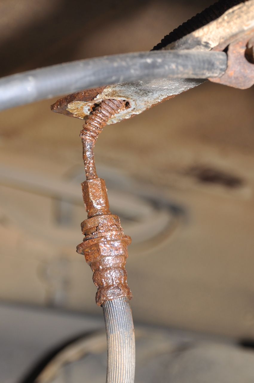
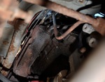
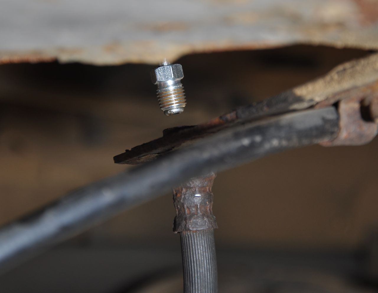
Original problem. The brake line looked just a little
bit too corroded to take the van on a cross crountry trip.
|
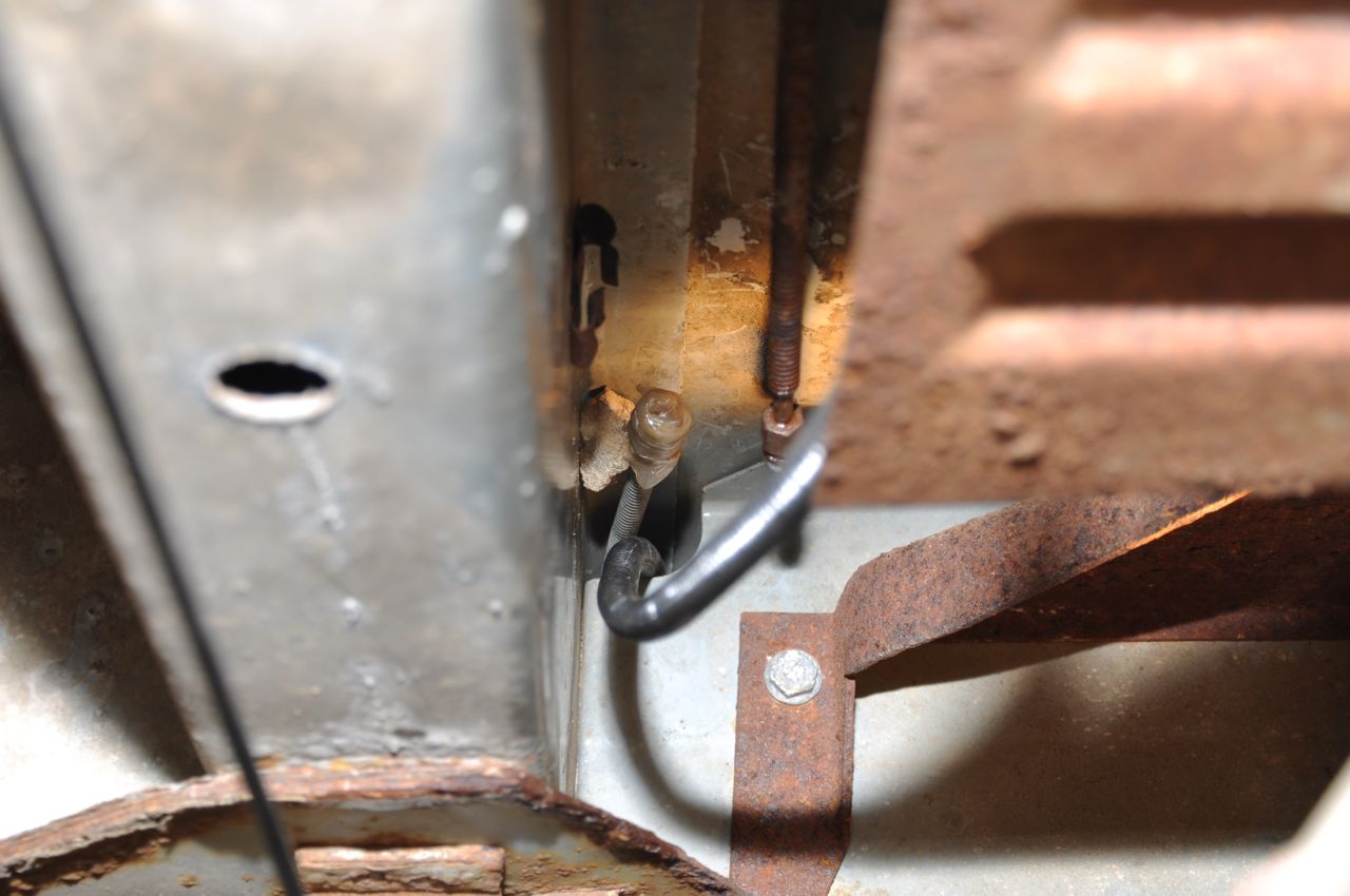
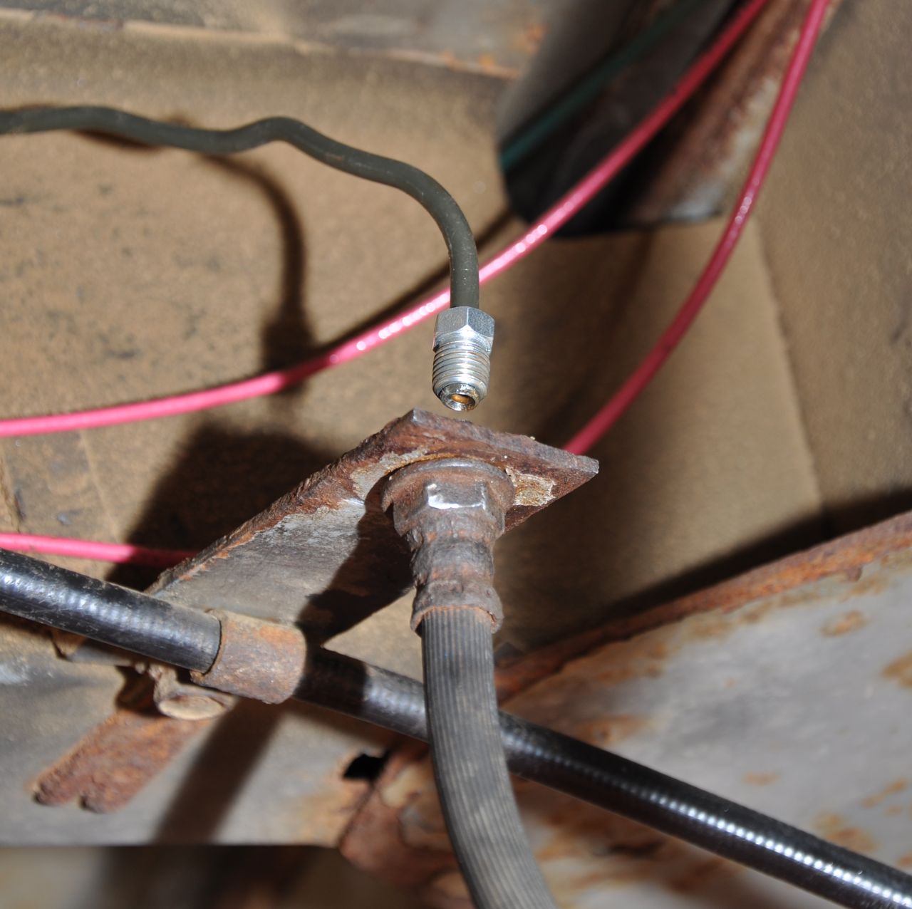
Pulled
the front coupler loose. You can see the clip and a little stone
I used to hold the line out away from the van body. The fluid
source side is wrapped in Parafilm to keep it
from leaking.
|
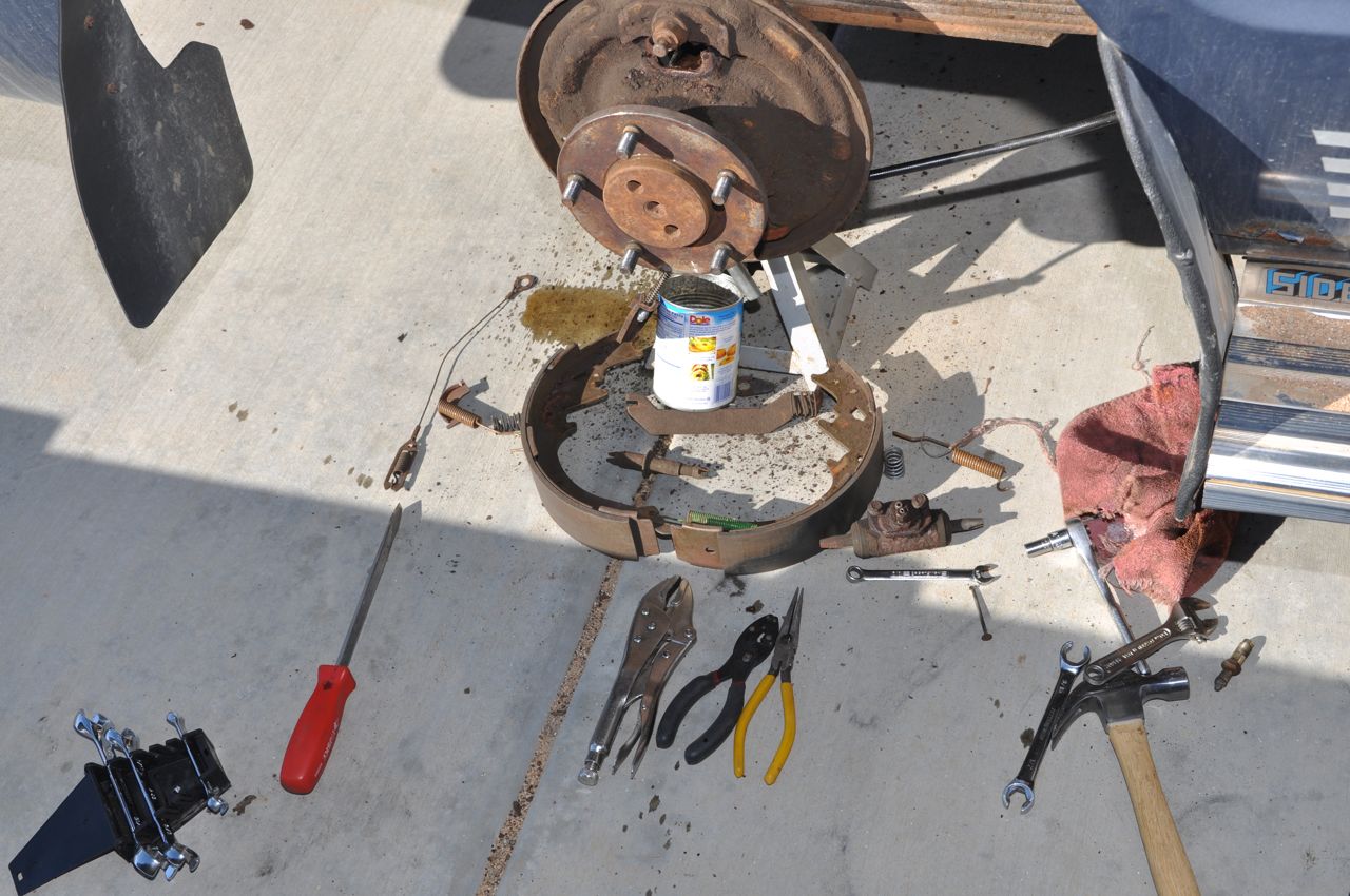
Work area on the right rear tire.
|
When I was bleeding the back
passenger side brakes, the bleeder valve broke off.
|
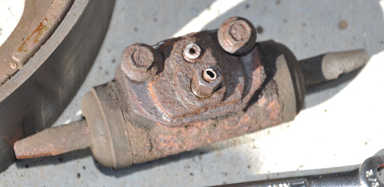
I
bought a new drum brake hydraulic actuator ("wheel cylinder") and
pulled the bleed valve from that one. It was much different in
size. Picture shows old wheel cylinder with brake line removed,
showing a shiny brass colored compression fitting seat.
|
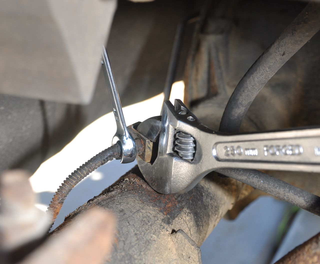
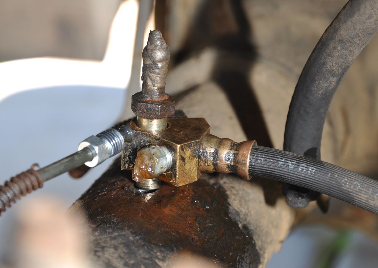
In
order to replace the wheel cylinder, I had to disconnect the brake line
- which broke, so now I needed to disconnect the brake line from the
fluid divider mounted to the reare axle. After unscrewing the
axle vent line tub, the brake divider could be lifted up enough to grab
it
|
On
the right is the line nut that did not seat enough threads. Plan
B is on the left, which worked fine. I could have gotten a taller one -
the important part is that the threads run down all the way to the
bottom.
|
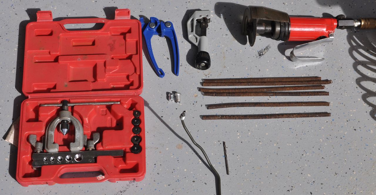
Tool
kits to make new brake lines. The anti-chaffing sprinks were wiggled
off the old lines and then cut into pieces to easily slide onto
locations where the clips will grab the new line.
|
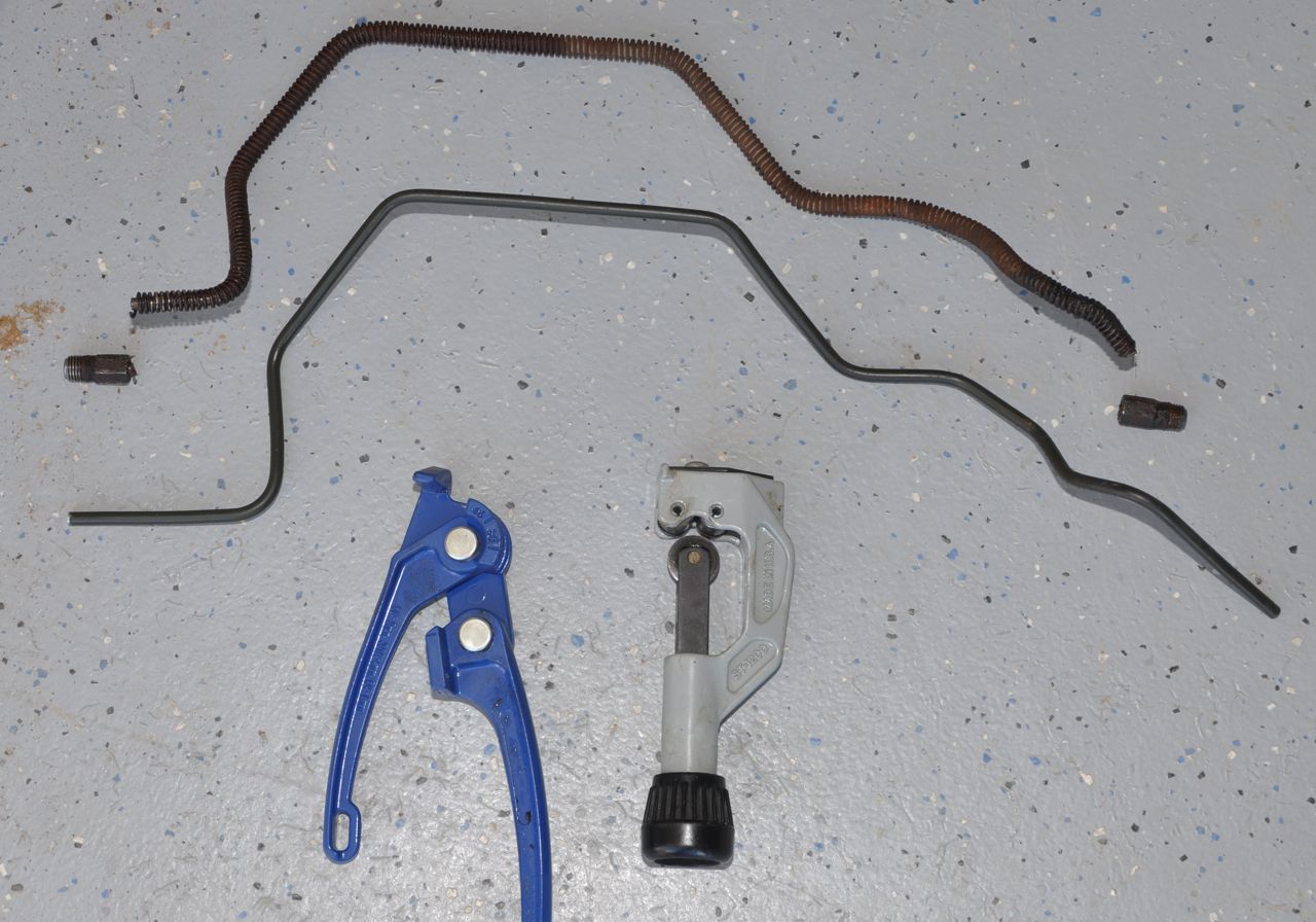
Old
brake line at the top (with nuts broken off becuase they were too
rusted to turn). Bottom is the new line. With no flares or
nuts, check the fit and bend/cut as necessary.
|
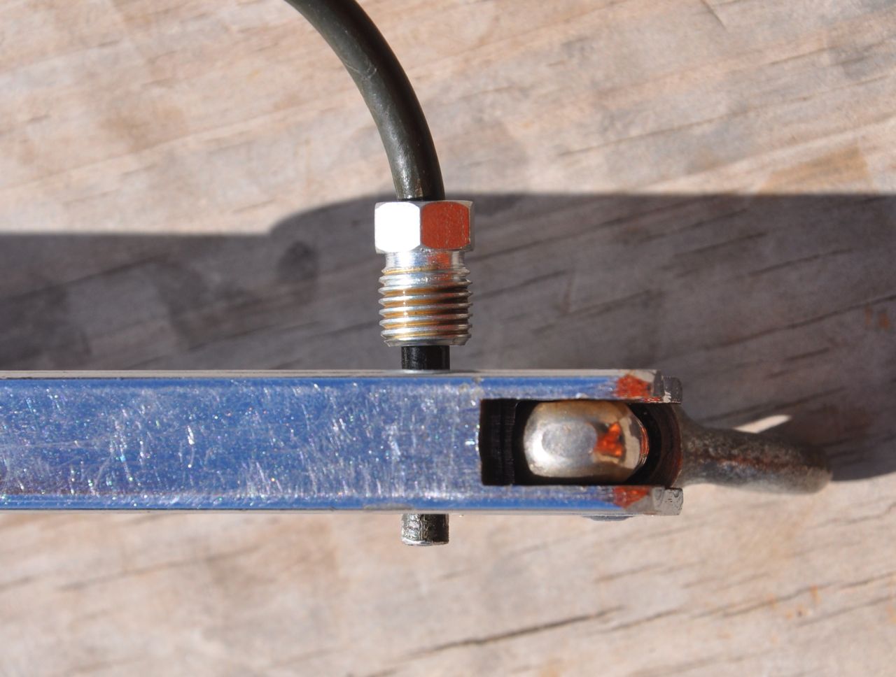
First step in double flaring a
tube. Clamp the tubing end after sliding springs and nuts on.
|
Second step in making a double flare
is pushing teh 45 degree polished point into the end.
|
New double flare on the end of the
brake line.
|
I made several mistakes with wrong
nuts and wrong lengths and bad flares.
|
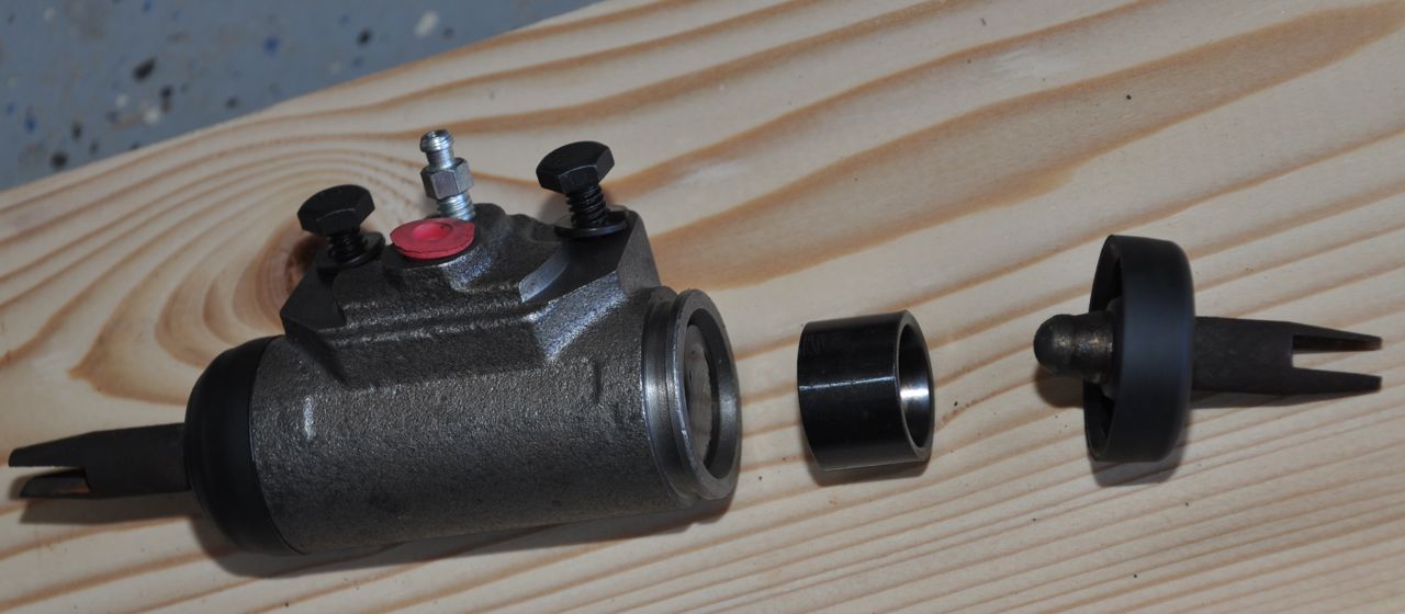
This
is the new wheel cylinder about to get bolted into position on the
brake housing. The cylinder cups came new. The rods out
each end were salvaged from the old cylinder.
|
New
line into position where the original problem was first noticed near
the back axle passenger side. Viewed from the wheel well.
|
New long line into position where the
original problem was first noticed near the back axle passenger side.
Viewed from under the van.
|
New short line into position near the
rear axle fluid divider. Connections are again wrapped in Parafilm until I'm
ready to connect them to prevent oozing out lots of brake fluid.
|
Parts photo, so I know how everything
mounts.
|
OriParts photo, so I know how
everything mounts in order to replace the wheel cylinder.
|
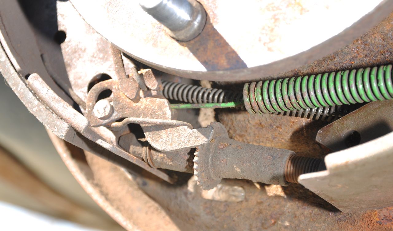
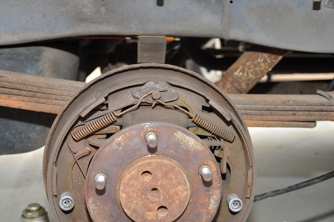
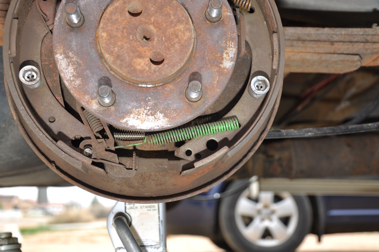
Passenger
side rear brake adjustment. I can never remember which way to
move the tooth gear when reaching in with a screwdriver, so this
picture is to help me remember!
|
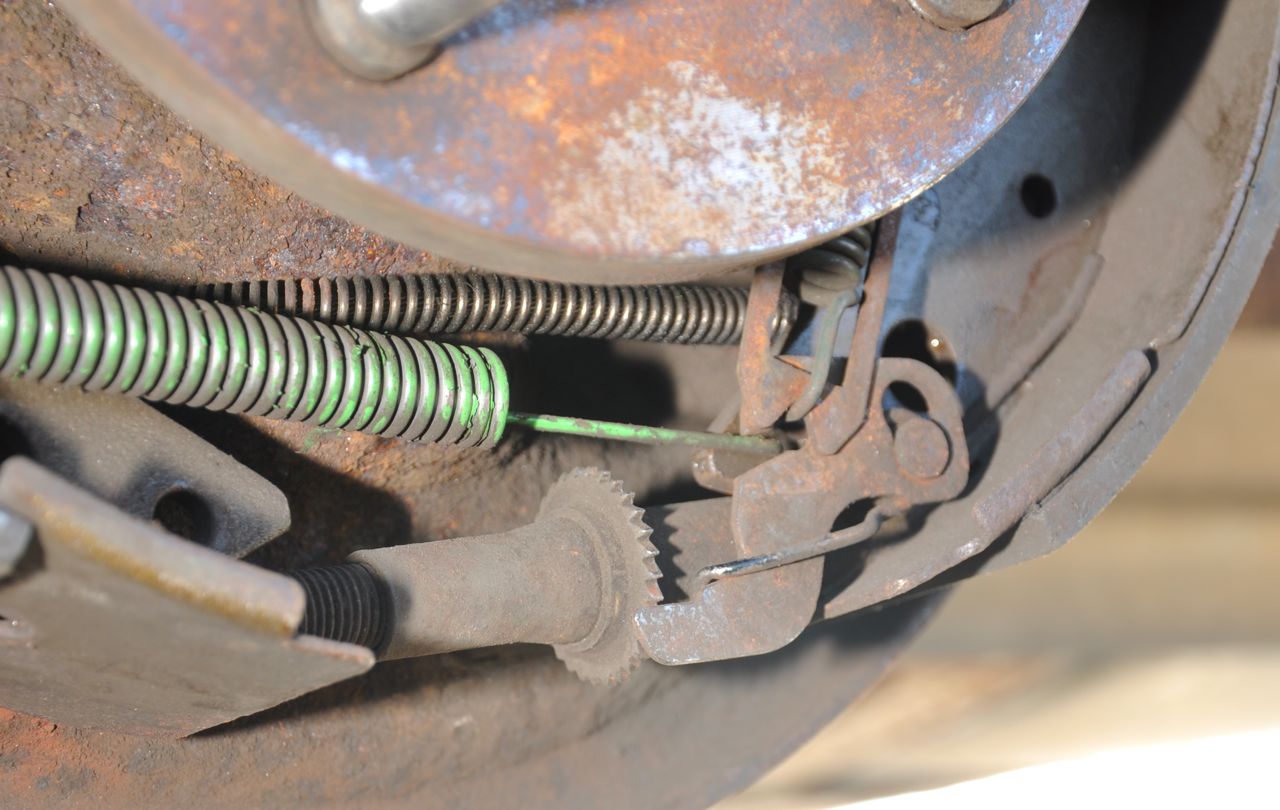
Driver side rear brake
adjustment. I can never remember which way to move the tooth gear
when
reaching in with a screwdriver, so this picture is to help me remember!
|
February 2015 - Electronic Trailer
Brake Controller:
Back to the electronic trailer brake controller.
There was lots of tedious work. Of course, a brake wire had to be
run to the back bumper. This comes from the new controller
mounted on the instrument panel of the van. When I used only the
trailer mounted battery separate from the vehicle to actuate the
brakes, the brakes took about 4 amps, so I figure that's about what
would be pulled through this new wire.
I also decided to run a hot 12-volt line fromt the battery to the back
in case I wanted
to run any systems and to keep the brake break-away backup battery (say
that 5 times quickly!) charged.
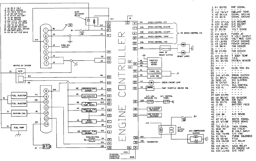
 Finding the switched brake line
operated by the brake pedal in the van proved to be a problem for
me. I
initially used the White
w/Pink wire because the Engine Controller schematic above shows it
comes out of the ECU (signal D40, pin 29) and goes to two brake
lamps. It seemed that this is what I wanted because it would be
used
to light up the brake lights and this is what the controller
needed. After connecting, stepping on the brake worked fine
(the brake controller LED stepped up in intensity slowly bringing the
trailer brakes on line). However, when I used the manual
slider switch on the brake controller, the fuse I installed feeding the brake
controller popped.
Finding the switched brake line
operated by the brake pedal in the van proved to be a problem for
me. I
initially used the White
w/Pink wire because the Engine Controller schematic above shows it
comes out of the ECU (signal D40, pin 29) and goes to two brake
lamps. It seemed that this is what I wanted because it would be
used
to light up the brake lights and this is what the controller
needed. After connecting, stepping on the brake worked fine
(the brake controller LED stepped up in intensity slowly bringing the
trailer brakes on line). However, when I used the manual
slider switch on the brake controller, the fuse I installed feeding the brake
controller popped.
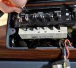
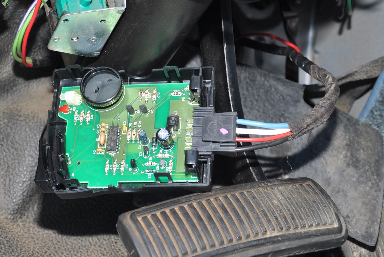
I opened the case of the
controller to see what I had fried. Fortunately all looked okay.
So.. out came my voltmeter and I took apart the
switch on the brake pedal and documented what's what. Turns out
the White w/Pink is hot all the time. Hmm.. This doesn't
seem to match the
schematic.
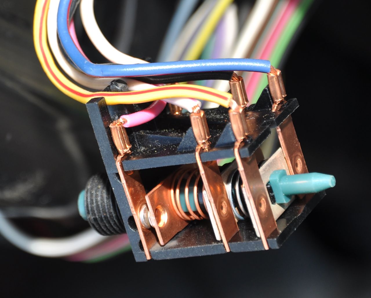
The brake switch is a 3-pole
switch. Two of the poles are NO
(normally open) and one is NC (normally closed). When the button
is pressed, the NO poles operate first and the NC operates
last. That said, the NO and NC descriptions are electrical
descriptions for the switch,
out of circuit. As installed in the van, the switch is normally fully
compressed and when you press the brake pedal fully, it's released to
it's normal status.

 The
normal switch normal is reversed
operationally for the brake switch. The NC is usually open and
closes first when when the pedal is pressed. The NO poles then
open.
The
normal switch normal is reversed
operationally for the brake switch. The NC is usually open and
closes first when when the pedal is pressed. The NO poles then
open.
White - NC - Pink
Black - NO - White w/Pink stripe
Blue - NO - Yellow w/Red stripe
The Pink wire carries battery power to the switch even when the car is
off and the key is out of the ignition. For me, it was 12.1 volts
with the engine off and 13.5 volts with the engine running (alternator
was raising the voltage). When the brake pedal was ~not~ stepped
on, this pink wire fed voltage to nothing. When I stepped
on the
brake pedal, the NC usually open connection was closed and the white
wire received the 12 volt power. I connected the brake controller
to the white wire and now it works fine.
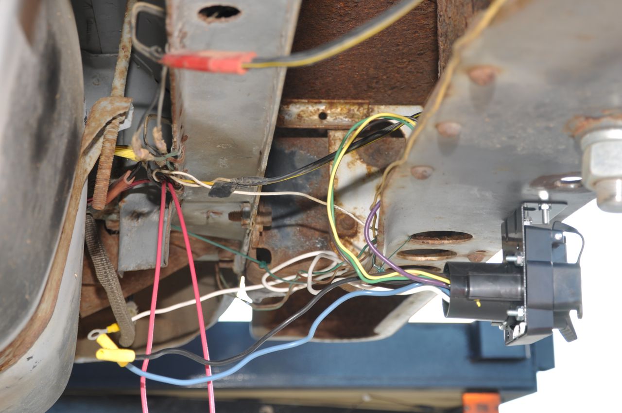
I purchased a bumper 7-wire trailer connector, and added to the
rat-nest of wires tucked into my rear bumper!
Pending:
Replace the A/C compressor and other things that came with the kit
remains an open item. Commerical estimate was $1200 even with the
parts provided and that is unreasonable considering I did it for a Ford
Aerostar one Saturday morning using a compressor salvaged from the junk
yard.
Also, the top and front panels of the an need a paint job or they are
going to start showing deep rust spots instead of blemishes. $600
estimate, but I'm not sure it's worth the super nice job the car
restorer is capable of. I'll probably sand blast, air disk sand,
spray prime and mostly match the color with whatever paint I can get.
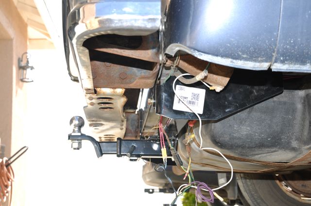
April 2015 - Frame Hitch:
After driving the 18' car
hauling trailer around for a few days, it became clear that using the
ball on
the step bumper made the metal plate flex. Several people
reminded that flexing metal over and over makes it fatigue and
fail. Building up the bumper would have taken a lot welding
skills I don't have. Instead, I purchased a frame mounted hitch,
which I had avoided doing because all the manufactureres say the hitch
can't be
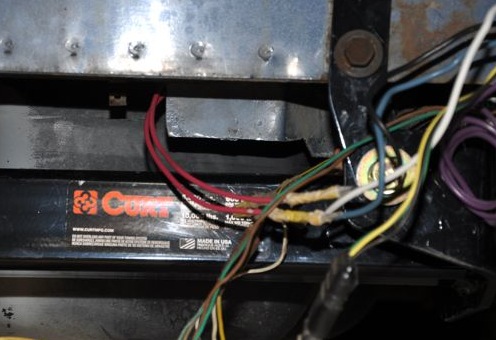
used with the step bumper. After comparing several brands, I
settled on a Curt hitch,
http://www.etrailer.com/p-C13041.html
I was fully prepared to travel
across the country with no bumper on the van because the trailer would
be connected the entire time. However, things worked out better
than
expected. The step bumper is bolted to the vehicle with 4
horizontal bolts on the left and 4 horizontal bolts on the right
side. The bumper has to be installed after the hitch, which uses
only 2 bolts on each side. By inserting 3-4 spacers (washers)
between the
van and the bumper on the bolts the new hitch hangar did not use, the bumper could be
mounted in the same place, only about 1/8" aft. I also had to
grind away about a 1" x 1/8" strip
of metal edge from the body frame as explained in the hitch
installation instructions, but this is unrelated to using the
bumper. No drilling was required, but I did
use a high pressure air hose and blow out a lot of dirt and stones from
the body frame before inserting the bolts.
I don't see any reason spacing the step bumper backwards about 1/8"
with
spacers caused any problems, so after removing the bumper and
installing the hitch, I put the bumper back on the van. To
be clear, the Curt C13041 hitch DOES
work with the factory step bumper if you space the bumper backwards a
fraction of an inch.
To see full-size images of frame hitch
installation, right-click and
open in a new tab.

The hitch was heavy, so I bolted up
one side with a hangar single bolt, and then swung the other side
up into position.
|
This shows the metal flange that
needed to be cut away so the hitch would ride up high against the frame
mount holes.
|
Size of the piece removed. This
was done on the left and the right side.
|
How
do you get a bolt through the washer and then through the frame from
the inside of the frame? Screw on a 2' section of music wire and
fish that through the hole first.
|
This
shows the music wire pulled down through the hole; the bolt follows and
a little wiggling makes it seat properly into the nut.
|
This shows two left-side bolts
installed with nuts and the third one pulling through.
|
After
the bolts are pulled through, ready to receive nuts. Screw the
nuts on carefully or you'll push the bolts back up into the frame.
|

This
shows the new washers installed to equal the thickness of the hitch
hangars, allowing the step bumper to be bolted back into place.
|
I was prepared to notch the step
bumper to clear the ball, but it has just
enough room to allow the trailer tongue to drop down over it.
|
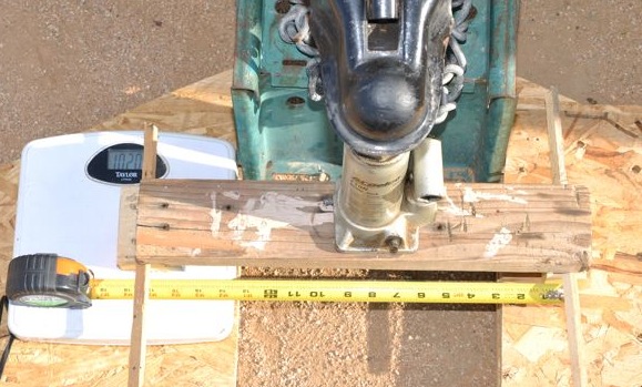
Bonus
picture! (Not about hitch installation). The tongue weight
was too heavy for my bathroom scale, so I made a little lever arm,
measured the distance and calculated the weight of the tongue.
|
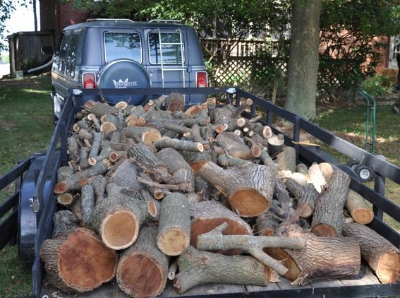
October 2015:
And the trailer weight winning
trip so far is when we used the van to move about 1 cord of
firewood. The trailer with the homemade sides installed is 18' x
6.8' x 2', or 245 cubic feet. A cord of neatly split and stacked
wood is 128 cubic feet - about half the trailer volume. I figure
the trailer would have been about half full if the wood had been
split and neatly stacked on the trailer. Firewood weight
estimates say a cord would weight about 3800 lbs.
The Class III hitch worked fine. Without a scale for the
tongue weight, I notice how high the hitch is before loading and load
the trailer so it drops down about "400 pounds worth". There was a spring left
in the suspension and handling was fine. Dual
axle electric brakes worked great when I adjusted them to gently feel
the braking when only the trailer brakes are applied.
4820 lb van + 1900 lb trailer + 3800 lb wood + 340 people => 10,860
lbs.
This was enough wood for about 1/3 of the annual heating needs of the
house. With fuel oil it's about $1,875 / yr, so this trailer load
was about $625 worth of heating after splitting it. Commerical
firewood was $150-$185 per cord, so that's the replacement cost value
of a 1 cord trailer load.
2016:
So far, the tow hitch has done well and this has become our work horse
vehicle. Two heavier trips were:
4820 lb van + 1900 lb trailer + 1760 lb cargo and Cessna 140 airplane +
170 people = 8,650 lbs.
4820 lb van + 1900 lb trailer + 2600 lb tractor + 340 people = 9,660
lbs.
The
van has moved about 8 trailer loads of wood - at least 10 tons.
Everything is working fine. The 3/4-ton B250 frame is doing as
well as a new Chevy 1500, Ford F-150, Dodge 1500. In
March, the Ram Van Wagon and trailer was used to bring home a 2600
lb Massey
Ferguson GC2310 front loader and backhoe. You can read my
other webpage about the GC2310 repairs.
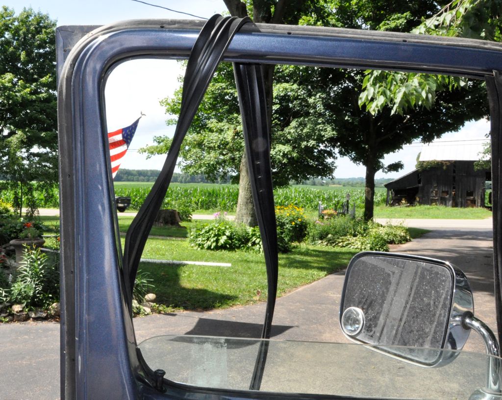
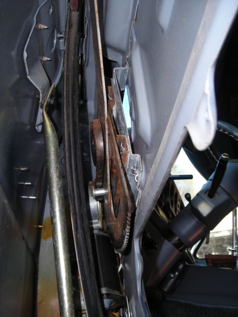
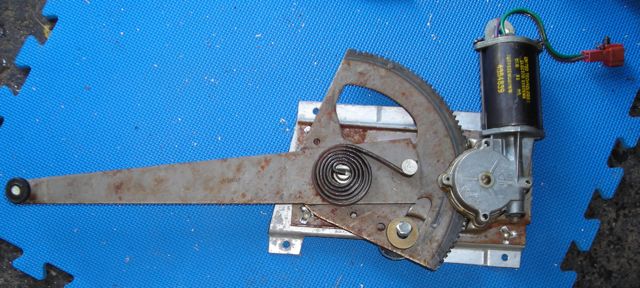
September 2017 - Window Regulator
The driver side window quit going up
or down. I can hear the motor spinning, but no window action!
To fix the window, removing the door asthetics was pretty easy down to
bare metal. The only difficult situation was the powerful spring
that gives some up-force to the window - which makes it more balanced
for the motor to lift up or pull down. Because the internal motor gears
were broken, nothing held back the powerful coil spring trying to
rotate the arm. Unlike many scissor lift
regulators, the 1989 B250 has only one arm that reaches to the window
rail and it pivots against the motor assembly, which is held to
the door with four rivets.
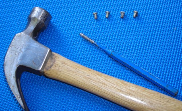
After taping the window up into position so it cannot fall into the
door, I punched out the middles of the four rivets using about a 3/16
punch. To
remove the motor unit and window lift arm, first the steel core of the
rivets were punched out. The second picture shows the little
rivet heads that fell into the door with the punch and hammer.
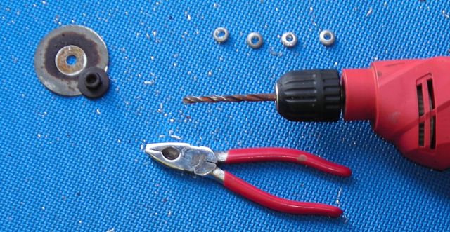
After the cores were removed, the
rest of the rivets were drilled out. I
used a 15/64" drill bit. Use a crisp plier to grab the head of
the rivet as you drill so it will not spin. Use a new or sharp
drill bit so it does not snag or grab on the rivet. When you
break through, tilt the drill a little up, down, right, left until you
cut away enough rivet for the head to be pulled off.
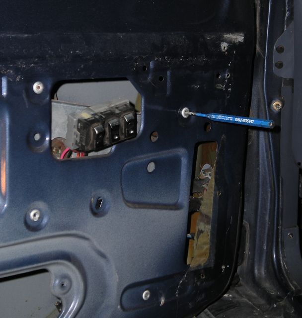
The big washer and nut in
the third picture were removed from the outside
bottom of the door. They secure the bottom of the forward window
track
and if they are removed, the track can be wiggled around to make the
motor fit out easier. Be sure to install the eccentric bolt post
back
in the same angle position when re-assembling so the window track is
set correctly to not warp or twist the glass window when it comes down.
If your drive motor gear
is broken, the motor cannot hold the position of the lift arm, so the
third rivet you drill will be under tension because as soon as its
free, the whole motor assembly will rotate on the last rivet and
attempt to "clam shell" close against the lifter arm - that's the
spring doing its job without any gears to hold it from moving.
Turns out at the very end of the toothed
gear you can see, there is no tooth notch in the last position, so the
clam shell closing action gets stuck on the last tooth of the
gear. Confirm this is true (no pressure on the clam shell
closing), then drill out the last rivet and the motor assembly will
drop down into the door, which allows the window lift roller to come
off the edge of its track.
Manuever the entire assembly out of
the door.
Before unbolting the
motor from the arm assembly, you need to remove the gear tension from
the motor drive
shaft. Press the arm and rotate it until you can stick a bolt
through the hole and lodge it against the motor frame (see in the
picture above). Then you
can safely unbolt the motor.
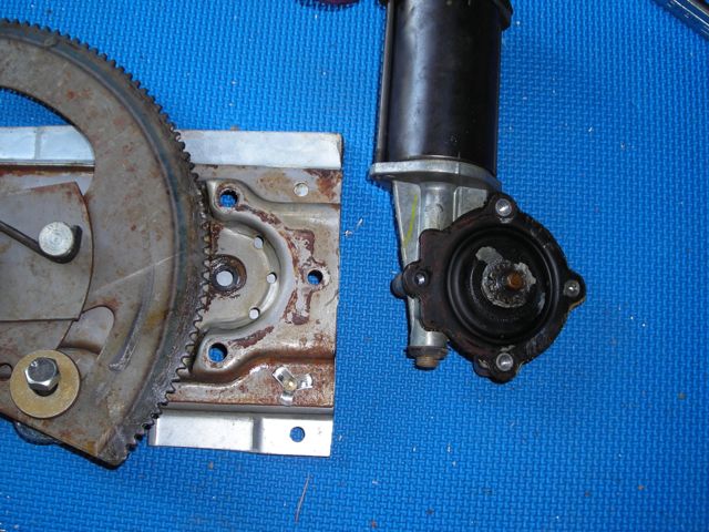
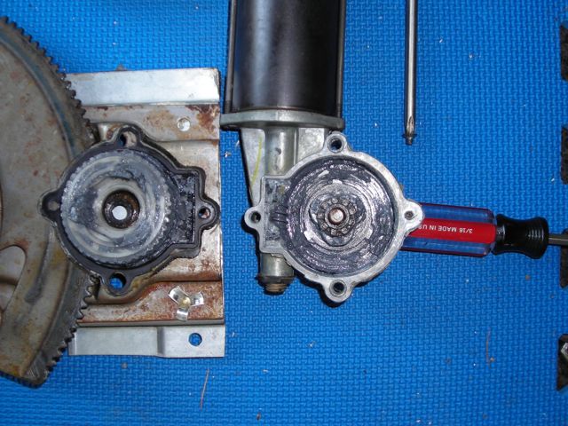
After removing the motor,
the fourth bolt position is secured by a screw only accessible after
you remove the motor from the frame. A phillips screwdriver
easily removed the screw. Gently peeling the rubber/fiber seal
off the face of the gears reveals the gears on the inside which
disintegrated like every body else's. I ordered new gears..
Turns out the near gears,
purchased from Rock Auto were 8 pieces: a plastic outer gear, and inner
metal gear, 3 bumpers, an o-ring for the shaft, a gasket cover, and a
plastic bag of grease. The bumper parts that had been shredded
look and feel exactly like hardened wood glue in the stem of a bottle
when I forget to put the top on! They're little 0.5" diameter
cylinders bumpers, 0.45" tall. I would try making my own next
time.
The old gear sealing gasket had 3 positions secured by the mount bolts
and the last position was secured by a flat head screw. Turns out
the new piece was incorrectly made with a hole too big so that the flat
head screw secures nothing when installed (it just sits in the cover
hole). I considered using the old gasket but maybe it was a
little torn in the middle and may have had a slightly different shape
rubbing against the gear. The screw has very few threads and small
clearance against the big gear arm, so I could not use a metal washer
to hold the gasket down. Instead, I used a nylon washer and I
hope it will stay in position. If the screw backs out, it will
jam against the big gear arm and make scrappie noises or just twist
sideways and bind up the whole mechanism. I wish the replacement gasket part part
had been designed right.
When you install the new gears and bumpers, the clamshell close
pressure will be gone; the motor holds the gear into
position. However, you should connect up the motor connector and
run the control arm almost to the end of the gear because the entire
assembly fits in the door better that way.
I put the roller track wheel into the window track and connected one of
the four bolts (using bolts instead of original rivets). Then I
carefully tapped the window "up" and "down" which, instead of moving
the taped-up window, made the motor assembly change position and
perfectly align the other 3 bolts.
I jostled the front window track around until the window tracked
without a lot of pressure or torque, and then tightened down the big
washer and nut on the bottom exterior side of the door.
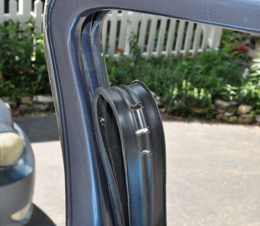
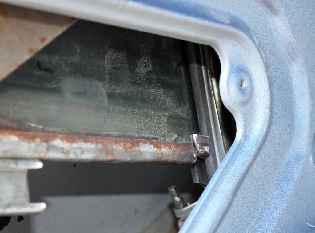
The only problem is that the aft window felt guide inside the door is
torn. When the window opens (descends), it doesn't go intot the
track. Instead it pushes in between the metal track and the
rubber felt liner. I need to get a new window rubber/felt.
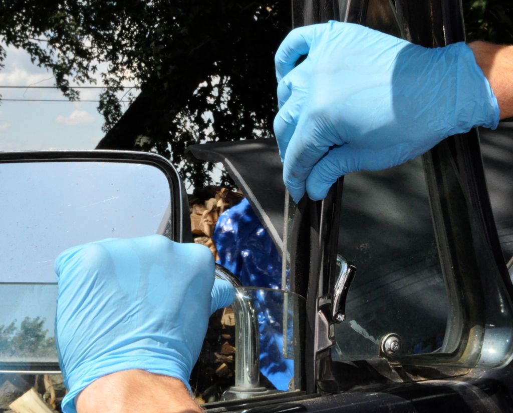
So.. uh... 9 months later I finally got new window rubber/felt runners
and had the time to install them. I purchased the kit made by
Fairchild Industries, part #KD1004, from Rock Auto for $35.78 including
shipping. Two for the left window and two for the right window
(although I only did the left window at this time). One is
shorter and goes on the forward side of the glass and one is longer and
goes on the rear and top side of glass.
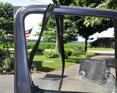
After
pulling the old rubber down and away from the metal window frame, it
was loose enough to "slide up" from the interior channel. The new
rubber was fed down the channel on the rear side of the glass.
|
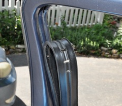
The upper
corner of the rubber was marked with 3 perforations that helped the
rubber go around the corner better.
|

Here's
the technique to slide the rubber down the channel around the
window. Lift the window up into the new rubber, then pinch the
rubber snug around the window and slide them both down. Then pull
the window up. Repeat.
|

Aha!
the real culprit causing all the original trouble. The metal
channel at the bottom of the window was off-center and sticking out too
far toward the front of the door. At the bottom and top, it
gouged the new rubber badly. I used Dremel cutoff tool to remove
about the last 1/4. The removed piece is staged in this picture
just so you can see it. Actually it fell off the end down into
the door. The remaining rounded edge of the glass slide nicely without
hurting the rubber.
|
September 2017 - Fuel Pressure
Some
time last summer, the van started needing longer and longer time
cranking to start - sometimes 10-15 seconds. If the engine is hot, it
may never
start. We almost go stranded at a rest stop coming back from
another state. This needs to be fixed. I imagine it's
either the
spark, or the fuel, or the air.
I
pulled each spark plug, re-gapped them and measured all the ignition
leads. Then I measured the DC voltage across the ignition coil
primary while running, and measured the ignition-off resistance of the
primary and secondary. All seemed normal. See the results
below.
Looking at the engine from within the van, cylinders are numbered left
to right, then front to back. Firing order is 1-8-4-3-6-5-7-2,
which is the same as the clockwise order around the distributor,
starting from 21 o'clock position.
Resistances of ignition wires:
Cyl 1 - 7.8 kohm
Cyl 2 - 12 kohm (boot cracked)
Cyl 3 - 8.6 kohm
Cyl 4 - 11.9 kohm
Cyl 5 - 6.2 kohm
Cyl 6 - 7.5 kohm
Cyl 7 - 6.6 kohm
Cyl 8 - 7.5 kohm
Coil DC voltage while cranking/running - 3 volt
Coil primary resistance when ignition off - 5.0 ohm
Coil secondary resistance when ignition off - 15 kohm
So I think I'm getting good spark on the plugs. With the air
filter removed from the top of the carburetor, I'm sure the engine is
getting air. So, moving onto the fuel...
I stared down into
the carbs while trying to start, watching what the fuel injectors
do. There was a little fuel spray
immediately wetting the butterfly valves while cranking the engine that
gets the car started. However.. after running for about 20
minutes (getting everything hot), and then trying to start, there was
NO fuel spray going down onto the butterfly valves for about 15
seconds. What?! That was definitely not right.
I pulled the fuel line off the carburetor body (the lower line) and
monitored the pressure. When the key goes on the second click,
the pressure hops up to about 3-4 psi and then back down to zero (when
the guage is not connected, a squirt of fuel comes out of the line
- maybe 1 cubic centimeter - but then the flow stops). If I move
the key to crank the engine, the pressure
slowly rises over about 10 seconds up to a stable pressure above 12 psi
(my gauge
goes only to 10 psi). When it gets up to the higher range,
fuel starts to spray out of the injectors and the engine starts.
Why does it take so
long to get fuel out when the engine is hot?
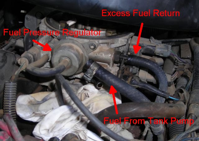 Just
to confirm this problem, I got a teaspoon of gasoline and when I
crank the engine with nothing happening, I toss the gas into the carb
and the engine immediately starts.
Just
to confirm this problem, I got a teaspoon of gasoline and when I
crank the engine with nothing happening, I toss the gas into the carb
and the engine immediately starts.
Is the fuel pressure regulator
on the carb body is not operating correctly? In normal operation,
it recycles fuel back to the fuel tank unless there is manifold
vacuum. More vacuum allows more fuel to the carburetor. I
disconnected the vacuum line, which is really nothing but a short 4"
tube right back into the throttle body throat. At idle speeds
with the air filter removed, there isn't any vacuum
in the throttle body anhow. Maybe cranking could cause a vacuum
and increase fuel flow?
So I applied a vacuum directly to the fuel pressure regulator while
cranking. No discernible difference. What is making the fuel
pressure so low for the first 15-20 seconds, and why does the pressure
go away before cranking the engine?
I also pulled the fuel return line from the pressure regulator.
When the
ignition is on, nothing comes out. Cranking the engine nothing
comes out. After about 15 seconds the engine started (when the
pressure gets high), and the engine started, and fuel starts coming out
under pressure. I tried to plug it with my thumb, but it just
sprayed fuel all over like a hose. I immediately stopped turned
off the engine and stopped cranking.
Plugged fuel filter? But it's almost brand new. I just
replaced it 1195 miles ago. Even so, I thought I'd check either side of
it.
I crawled under the car and did the same tests while someone else
turned the key and tried to start the van. From the tank, the
fuel line goes into the periphery connection on the fuel filter.
Measuring directly from the tank hose, behavior was the same as
measured at the carburetor. When I measured the
central line (labeled "OUT") coming out of the center of the fuel
filter, it also behaved the same as at the carbureator. Since all
the readings were the same, my
conclusion is that there is no
line blockage all the way from the tank to the carburetor.
Why should it take 15 seconds to get the fuel pressure up to 14
psi? Maybe the sock filter in the gas tank is
plugged. However, that doesn't explain why the pressure goes back
down to zero after turning on the
ignition.
After a bit more research, I found out it's suppose to work that
way! The ASD relay automatically cuts off fuel and ignition if
the
engine is not cranking. So it powers up for just a second when
the ignition is turned on and then immediately cuts off.
When the engine crankshaft sensor shows it's turning (with the starter
or any
other reason), the computer turns the ASD relay on.
I took the ASD relay harness off the relay and hotwired the contacts
closed. These are ASD terminals 30 and 87
in the diagram above,
which corresponds to the one blade that is perpendicular to the others
and the one opposite. Also see the picture below. The
fuel pump has a chance to get the pressure up and keep it up before
cranking. Turning over the engine immediately starts it. I
assume the
pressure rises slowly because the filter sock in the fuel tank is
plugged. It can't be the pressure regulator leaking fuel back to
the tank or it would just keep doing it and never let the engine start.
Later note - Chilton book has a
faster way to diagnose. Tap in for pressure checks after the fuel
pump before the fuel filter. If okay there, replace the fuel
filter (it is plugged). If pressure is still low, squeeze the
return line from the pressure regulator. If that raises the fuel
pressure, the regulator is leaking. If that does not raise the
pressure, the pump or the sock filter by the pump is bad.
I drained all the fuel out of the fuel tank to reduce the weight and
make handling it easier/safer. I
disconnected the tank fuel line before the fuel filter and ran a tubing
out to a gas can. I disconnected one side of the
ignition coil (so the battery drain wouldn't be too much). Then I
shorted the ASD relay wiring harness to mimic the relay closing - the
ignition of the car ignition doesn't even need to be on. This
made
the pump come on to squirt fuel into an external gas can.
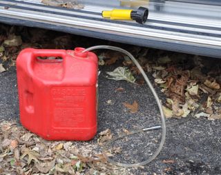
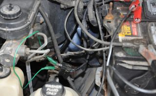
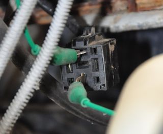
The middle picture is a picture of the engine compartment in front
of the driver - battery on the right side of the picture. The ASD
relay sits against the firewall. The closeup shows which two
wires of the harness I shorted after disconnecting from the
relay. The bottom connection in the picture is unswitched 12
volts. Be sure the other end of the jumper wire doesn't short
against the frame or other metal. While draining the fuel, I
again
tested the pressure. It does come up to 14 psi. It just
comes up slowly - about 7 seconds.
An alternative way to drain the tank is to remove the rubber cap from
the drain/siphon line coming out the top of the tank and poking through
the frame slot with all the other tubes. Just connect up a
plastic drain hose and start the siphon and the tank will empty out to
only a few ounces left. Notice the metal helical siphon line goes
to the verry bottom of the tank.
To drop the fuel tank, you need to use a 9/16" deep well socket more
than 3.5" deep to undo the nuts holding the
tank straps. Chilton says the bolts are suppose to stick below
the
nuts only 2-5/8±1/8" on the back and 1-7/8±1/8" on the side. Mine
are
way longer!
Later note -
I purchased a 6" deep 9/16" socket suitable for an impact wrench along
with a 6" extension. It cost me about $22 on the internet.
This didn't help much since the nuts were rusted tight and as I turned
them, the bolt heads were tearing out of their hook in the frame.
I ended up using a hacksaw to cut the bolts and fabricated new ones
with a blow torch and 3/8" stock carriage bolts.
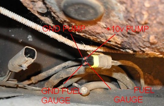 Putting
the car rear axle up on jacks, I crawled under the van to disconnect
all the connections to the gas tank. In addition to the obvious
fuel filler tube (and the vent pipe right next to it), there are other
connections shown in the picture. One is the electrical
connections for the fuel pump and tank quantity guage. Going from
left to right in the picture
Putting
the car rear axle up on jacks, I crawled under the van to disconnect
all the connections to the gas tank. In addition to the obvious
fuel filler tube (and the vent pipe right next to it), there are other
connections shown in the picture. One is the electrical
connections for the fuel pump and tank quantity guage. Going from
left to right in the picture
- Drain / siphone line with
a rubber cap
- Medium return line
- Small evaporative return
- Large supply line
- Electrical cable
Note the order because all the
tubes reach much better if you put them back through the frame slot in
the same order. To get the drain tube loose from the van
frame (so it could
be pulled out with the tank), I unscrewed a metal screw which was also
holding down an electrical ground wire.
To drop the tank, it turns out the bolts were so rusted I had to cut
them off with a hacksaw. Took time. Skinned my
knuckles. But it worked. I replaced them with new 3/8" bolts
7-8" long. You can see that some chipmunks had built a nest on
top of the fuel tank. The second top picture shows all the lines
connected and stopped off with little wads of cloth.
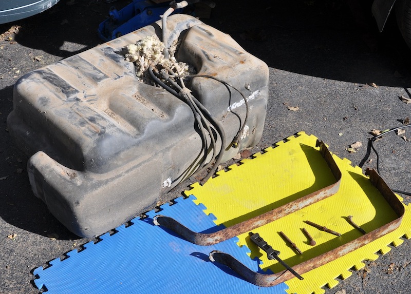
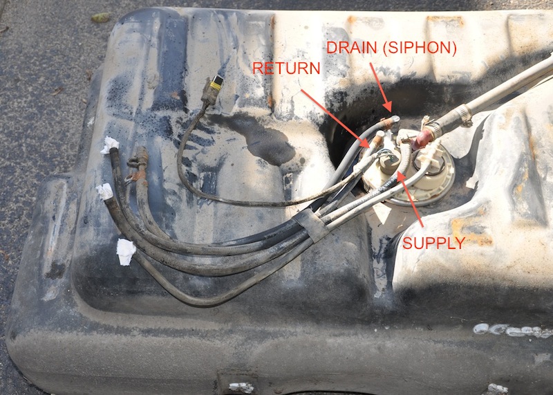
After loosening the collar
clamp, the entire tank assembly could be pulled upwards. The
brown plastic piece unclipped easily and I could get at the fuel pump
and the black sock filter. The excess fuel overpressure line
comes back into the top of the tank and the top of the brown submerged
container. It comes out the bottom, and makes a 90' turn and
blows into the chamber where the fuel pump is. This is shown in
the second picture below. What is strange is that the gasket
material was wet and mushy. I'm not sure why, but it appears that
it needs to be replaced. I can't think of any reason it should
intentionally be this way. Is this the effect of ethanol in the
fuel? Maybe a disintegrating gasket is what plugged up the sock filter
or goobied up the pump so that it came to pressure so slowly.
I replaced the gasket material with "fuel proof" material purchased in
a variety pack from a car parts store.
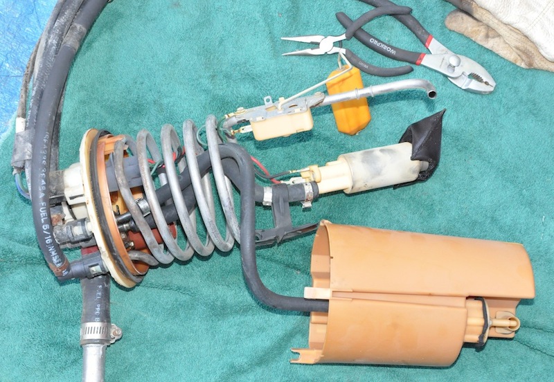
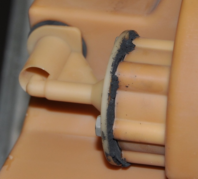
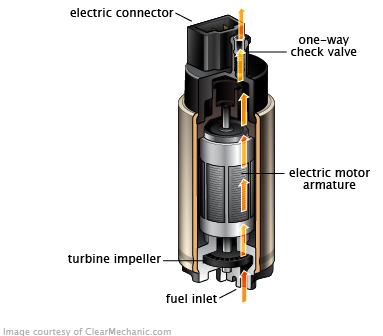
The new pump is spec'd at 52-70
psi. The manufacturer says this is the same as the OEM
pump. The pressure regulation is done with the regulator at the
throttle carburetor body in much the same manner as a thermostat
(spring lets excess pressure return to the tank).
Notes to put the tank back in...
Hook up the left/right cross strap first in the left hanging slot and
move it out of the way. Once the tank is up in place, you cannot
get this J-hook installed.
Get the fuel fill line and the vent line routed and connected with the
right side of the tank leaning down on a 4" block of wood. Then
with the tank tilted, reach your left hand in and grap the tubes and
push them one at a time through the frame slot. Do them in the
right order (see pictures above) so each hose comes out the right
length. There is not room to switch them after they go through
the slot.
Hook up the right fore/aft tank strap first, using a length of wood to
stick under the bracket and hold it up tight against the tank while you
install the nut holding up the strap. Repeat for the left
fore/aft strap. Then go back and install a nut holding the longer
left/right strap.
First time I re-installed the tank, the depressed well above the tank
(where all the connectors are) filled with gasoline and gasoline
spilled over the front of the tank in a little dribbly water
fall. I had to drop the entire tank a second time and check
connections. I used an old fuel filter to route the fuel from the
outlet tube back into the return tube and hooked a 12 volt battery up
to run the pump.
Don't hook the battery direclty to the fuel wires or you may melt the
little resistor wire on the tank guage float and
probably ignite the entire tank of gas making a big boom. I am
guessing the fuel guage resistor is fed with 12 volts but through
another resistor so the output voltage will change as the tank empties.
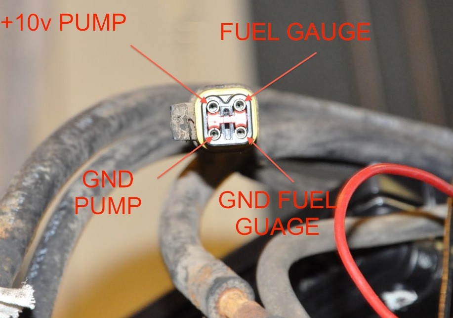 See
connections below. The pump should be about 5-6 ohms between the
pump pins, and the
tank guage resistor should be about 1-10 MOhm between the two guage
pins and change around as you
tilt the tank and move the fuel float. I have the voltages to the
pump noted
at +10v because that's what mine were coming from the van side.
In reality, these are
+12v connections with some voltage drop due to
long wires and weak battery.
See
connections below. The pump should be about 5-6 ohms between the
pump pins, and the
tank guage resistor should be about 1-10 MOhm between the two guage
pins and change around as you
tilt the tank and move the fuel float. I have the voltages to the
pump noted
at +10v because that's what mine were coming from the van side.
In reality, these are
+12v connections with some voltage drop due to
long wires and weak battery.
The fuel gauge non-ground
side also had about +10v on it but in the picture below I wrote "fuel
gauge" instead of "+10v" because I DON'T know it's okay to push that
much voltage across the gauge resistor. The van might apply 10v
through a separate resistor to the fuel gauge, and if you put a
powerful 10v source into the tank resistor, you might melt it. I
don't know. It would be really bad to melt the gauge resister -
make it hot like a filament - while it's around all that explosive
gasoline!
Nothing was leaking when I ran the fuel pump for a while. Only
the vent line seeped a little bit if I poured fuel into the tank vent
line. There's no way this should matter because the vent line is
filled with air. But when I put everything back, the leaking fuel
stopped.
It seemed like the van was working, but then the problem slowly
returned. I know it's a fuel issue because if I throw a
tablespoon of fuel into the carburetor, it starts immediately upon
cranking. Since I've replaced everything else in the fuel system
(pump and filter), it must be the pressure regulator or fuel
injectors. Since I have no trouble running or accelerating once
the engine is running and I can see a nice spray of fuel on the
throttle butterfly valve once it's running, this must be a TBI fuel
pressure regulator problem. Replacing this is a $50 guess, but I
don't see any other way.
I received a new PR188T Fuel
Injector Pressure Regulator, but when I tried to start the engine,
fuel
immediately started dripping out from around the regulator. This
will not work. Turns out there are three problems with this new
pressure regulator:
- Gasket sits in a recessed
area and the new gasket was 35 thousandths thinner (0.0615" vs. 0.0650")
- The ear mounting flange
was bent toward the mount surface so it bottomed out before the gasket
in the middle
- One of the two tubes going
into the carburetor block had a recessed surface around it so it didn't
squeeze against the gasket as much
The engine did not run better
with it installed, so I think I'll just return the regulator.
While things were disassembled, I measured the resistance of both fuel
injectors and they were each 2.6 ohms.
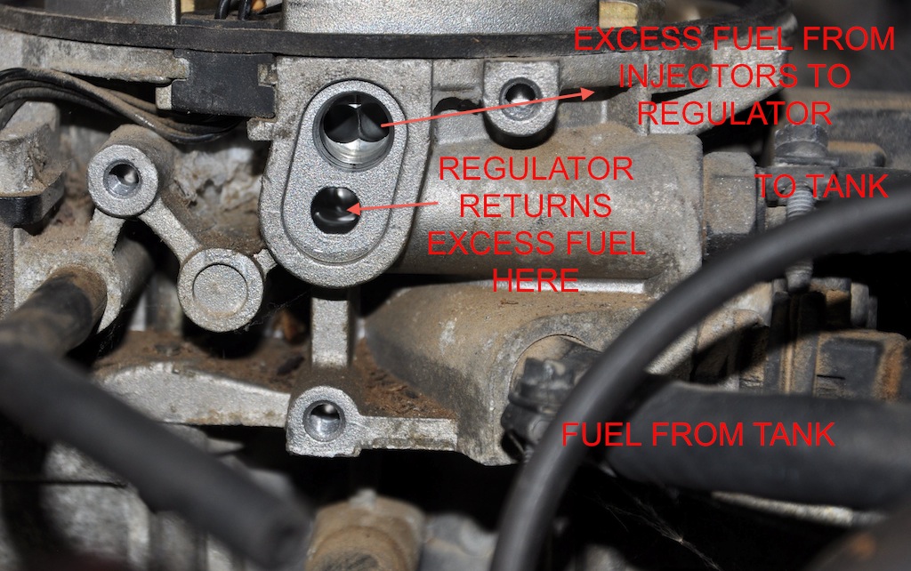
This
is where the fuel pressure regulator mounts. It's really rather
simple. Excess fuel comes from the injectors, and when it pushes
a spring diaphram open, it goes back to the tank. A vacuum hose
on the top of the regulator helps move the diaphram (lowers the fuel
pressure?), but wasn't pulling any vacuum during my tests.
|

With
the ASD relay hooked up normally, this is what happens. Notice
everything is dry upon the first key click, and a little fuel spray
after the pressure builds up for a while. Fuel pump doesn't come
on until engine is cranking.
|

Here's
the fuel pressure from going into the carburetor. My guage maxes
out at 10 psi so you can't see 14.5 psi, but notice the engine doesn't
start until the pressure gets up to about 10 psi.
Is the fuel pressure suppose to drop to nothing when the pump quits, or
is the system suppose to hold pressure? What does yours do?
|

With
pins 87 and 30 of the ASD harness shorted, the fuel pump is constant
running. When the ignition is turned on, a squirt of fuel happens
and the engine immediately start when cranking.
|
With
the old regulator back in place, I experimented a bit with the fuel
pump. The engine seemed to be running a bit better now, taking
only 5 seconds or so of cranking to start it up with cooler
temperatures. Hot temperatures are still difficult. See
the three movies above showing fuel injector sprays and fuel
pressures. The fuel pump is suppose to have a check valve that
prevents backflow of fuel. How come the pressure drops so fast
once the ignition is turned off?
Does your pressure take a long
time to come up and drop immediately back to zero when the ignition is
shut off? Maybe I'll put a 1-way check valve in the fuel line
after the fuel filter and before the carbureator. Or, maybe I'll
carry a jumper with me, and if it gives me any trouble, I'll short the
ASD relay harness. Well, wait, no.. that won't work because I
can't plug the relay back in once the engine running. Maybe a
parallel switch running to the dashboard so I can press a button to
force the pump on?
July 2018 - Suspension Bumper
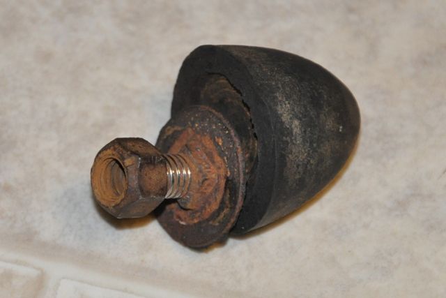 I
was crawling around the van doing fuel related work and noticed a
rubber bumper that had fallen off. Turns out this is the bumper
that mounts on top of the wheel control arm A-frame. The rubber
had separated from the mounting bolt and I was able to unscrew the nut
only with a long ratchet arm. After removing the nut, I hammered
the bolt out using a piece of aluminum to keep the bolt from being
damaged. I found a new one at Advanced Auto parts for $9.
I
was crawling around the van doing fuel related work and noticed a
rubber bumper that had fallen off. Turns out this is the bumper
that mounts on top of the wheel control arm A-frame. The rubber
had separated from the mounting bolt and I was able to unscrew the nut
only with a long ratchet arm. After removing the nut, I hammered
the bolt out using a piece of aluminum to keep the bolt from being
damaged. I found a new one at Advanced Auto parts for $9.
Air Conditioner Compressor and Roof
Paint
I have an A/C compressor in the
garage, along with other system parts. Now I need time to install
it. I should also paint the van before winter sets in
again.
Sold
I sold this vehicle Fall of 2018.
Financial Finale:
After the the costs incurred above, I
began to wonder what the vehicles
actually cost me and if it's worth my time to fix them. I've kept
mileage and repair and insurance data
for years and spent some time with a spreadsheet program to reduce this
to meaningful data. The answer has two parts:
1) I work on cars because I want to understand them and see
preventative issues and manage
the ownership of the vehicle rather than letting it manage me by
breaking unexpectedly. This management process probably saves money.
2) The big dollar issue, however, is depreciation cost. You
can stop depreciation cost
by being comfortable with older vehicles and being willing to handle
the
repair costs. This would happen even if you preventively did
nothing. To replace the capability of this older van with a
2-year old model would cost about $30,000. Figure if you keep a
vehicle for 10 years, that's $125 month in depreciation.
Click on the little graph here to download a
pdf document.
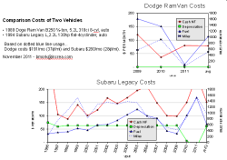
Additional Resources:
©
2010-2017 Brian Mork. Please
contact me using the copyright link prior to commercial use, or
reproducing for
distribution in a commercial context.
FOR
SALE: One live-tested fully working ECU PCM SBEC SMEC computer
for
a 1988
to 1989 Dodge van 6-cylinder or 8-cylinder van, $65.