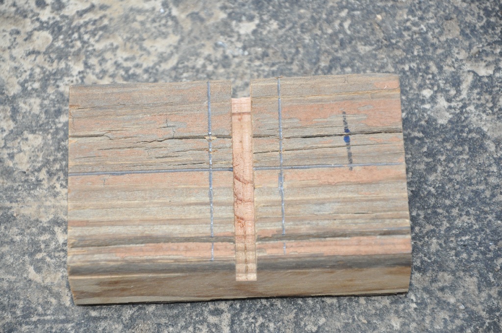
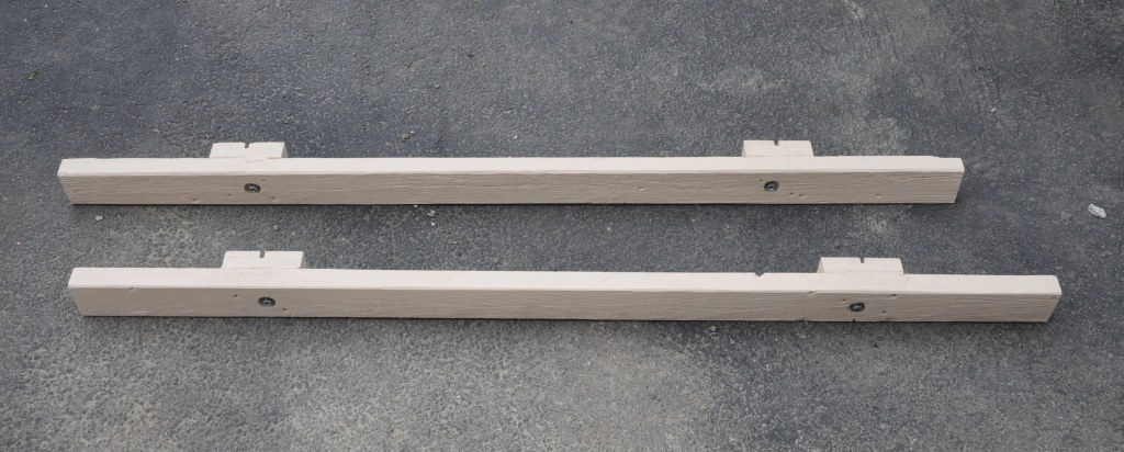
 Shows the support board with a
double-wide saw kerf 9/16" deep. Also shows guides marks to drill
two 5/16" J-bolt holes.
|
 After the support boards have saw
kerfs, test fit them in position and center the cross-beam support board.
|
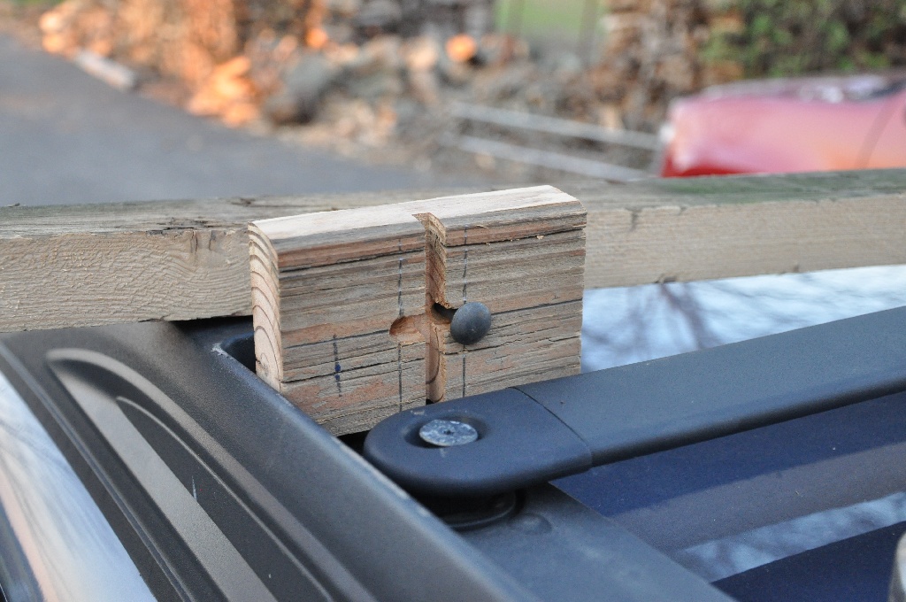
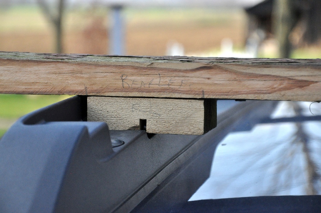 Mark where the support boards go on
one side of the cross-beam board. The picture was taken on the rear
left support. Notice there is zero clearance above the plastic
fairing of the factory luggage rack. I used a vertical 1/8" spacer board in the
final design.
|
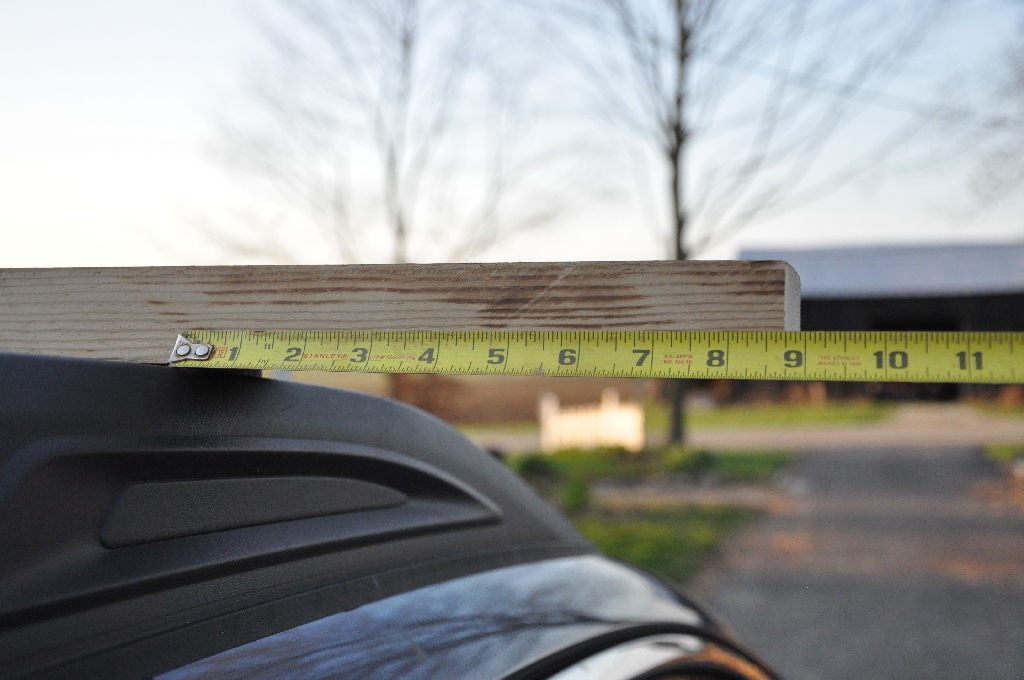
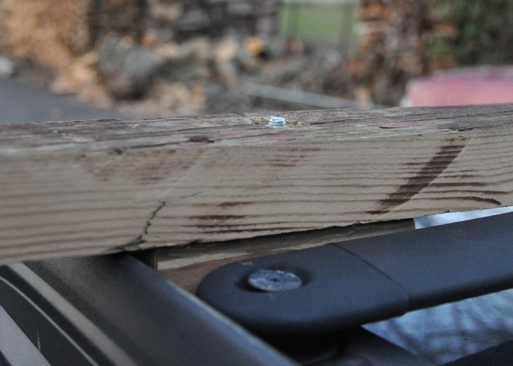
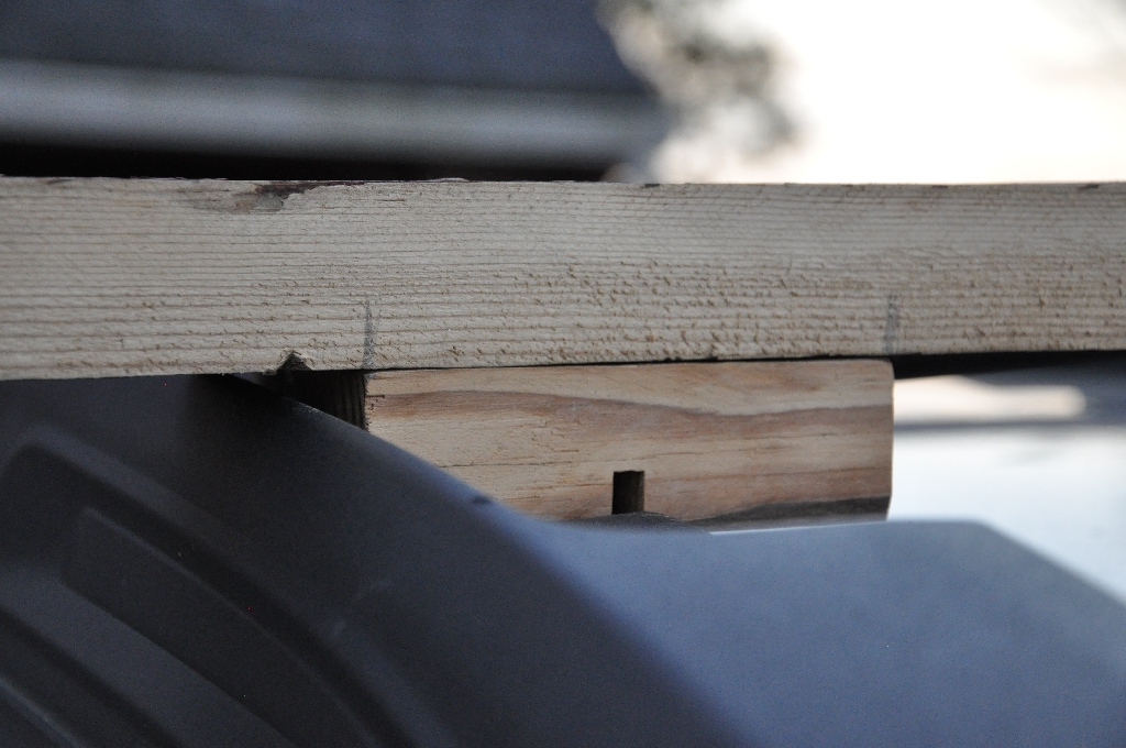 This picture was taken on the front right support. Notice
there is about 1/4" of clearance above the plastic fairing
of the factory luggage rack.
|
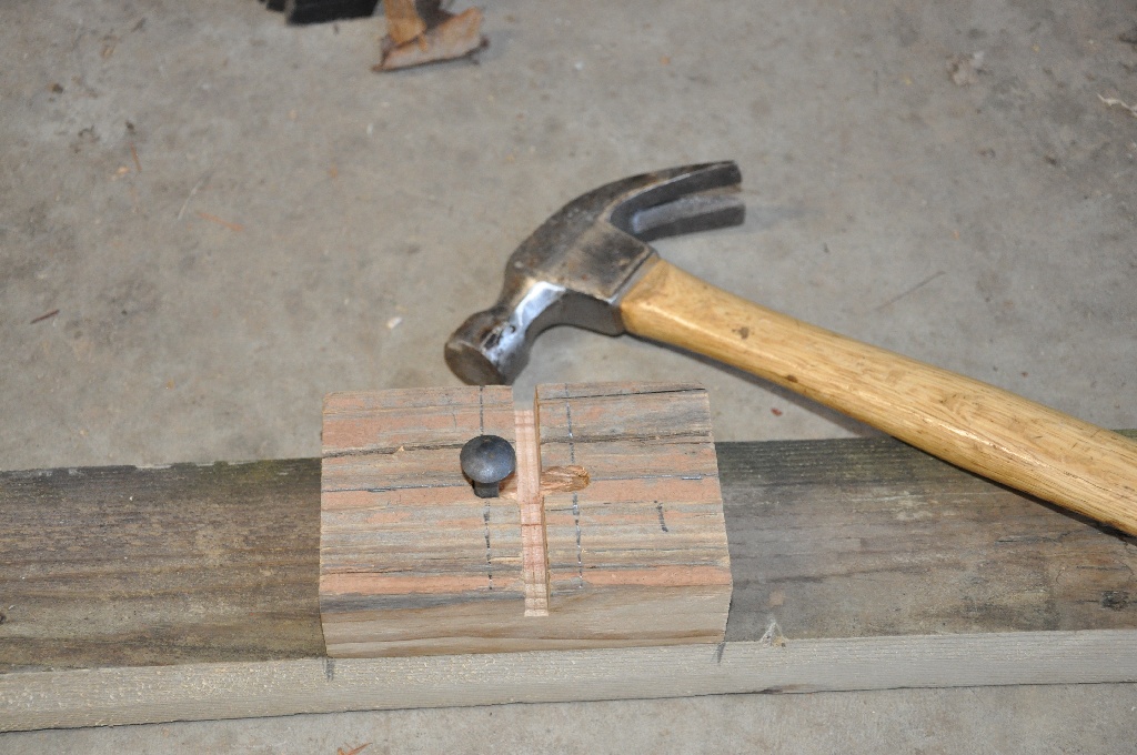 This
picture shows the support board bottom side, where the two J-bolt holes
have been connected together with a channel same depth as the saw
kerf. Because the J-bolts have round corners (not square), the
channel-to-hole edge is rounded a bit so that the J-bolt does not stick
out at all when inserted. The bolt in the picture is a 2"
straight 5/16" bolt. I hammer tapped into the hole to make a drill
mark on the cross-member board.
|
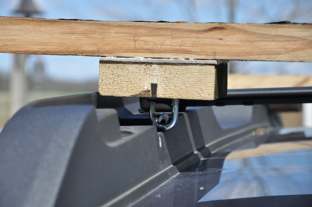
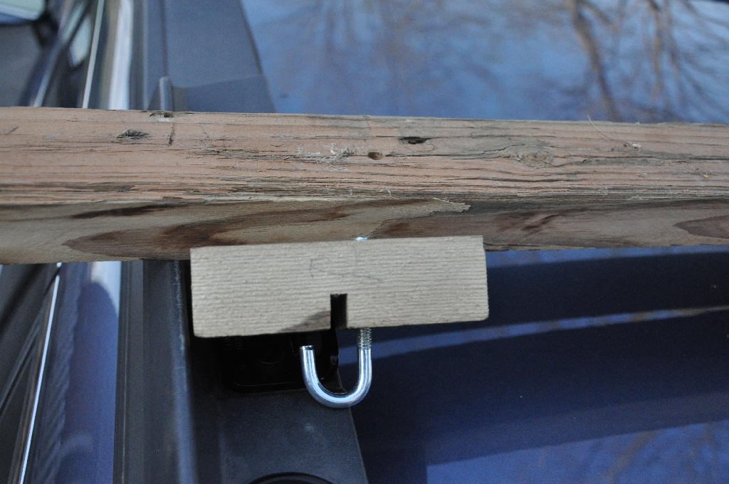 After
the support board has two holes and a J-bolt channel, and the
cross-member board has a through-hole, assemble on the hard-point mount
of the car. I designed the shaft of the J-bolt on the inboard
side of metal hard point bracket thinking I could get my fingers under to install the bolt better.
|
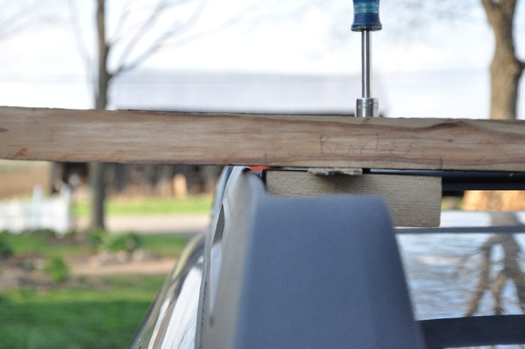
 With
one side test assembled (but without any nut on the J-bolt) position
the other side. This is a critical distance that is difficult to measure accurately a ruler. Don't bother. Use a straight 2" 5/16" bolt and lightly hammer on the
top cross-member board to make a mark where the hole should go.
|
 This
picture shows the test shim I tried on the back cross-member. In
the end design, I cut a shim the same size as the support board from
old 1/8" paneling and sandwiched it between the two boards.
|
 The
3" J-bolts stick out the top of the wood just enough to scratch
whatever is resting on them. I removed 4 threads with a grinder
from each of the J-bolts. Do this with the nut screwed on the
bolt so when you take the nut off, it cleans up the threads.
|
 I glued and screwed the two pieces of wood together. This is how the rack assembles onto the car with the J-bolt. Any glue joint misallignment was smoothed out with a wood plane after the glue dried. |
 Two coats of paint finishes the rack. Thinking about it afterwards, I would have used polyurethane so that the paint would not rub off on the plastic manufacturer racks. |
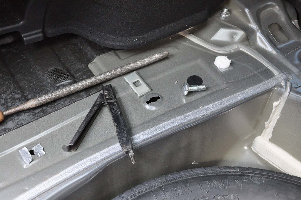 Tools
to make the access hole - a nibbler and round file. Notice the
square edge "wings" on the hole. That's what the nibbler does. To
get access to these holes, you have to unclip 2 difficult foam clips on
each side. See the narrative.
|
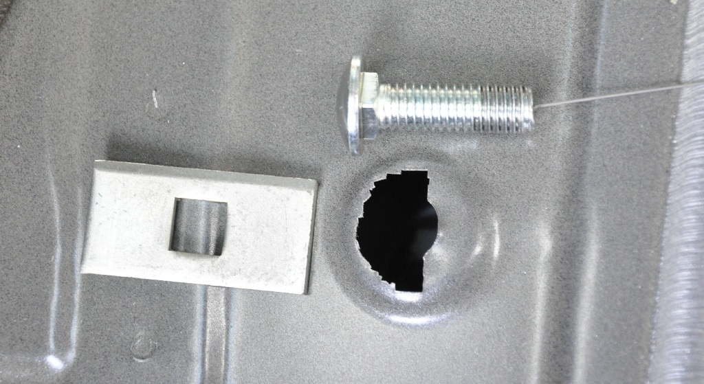
I tried making a half-moon instead of a full circle hole. Worked fine.
|
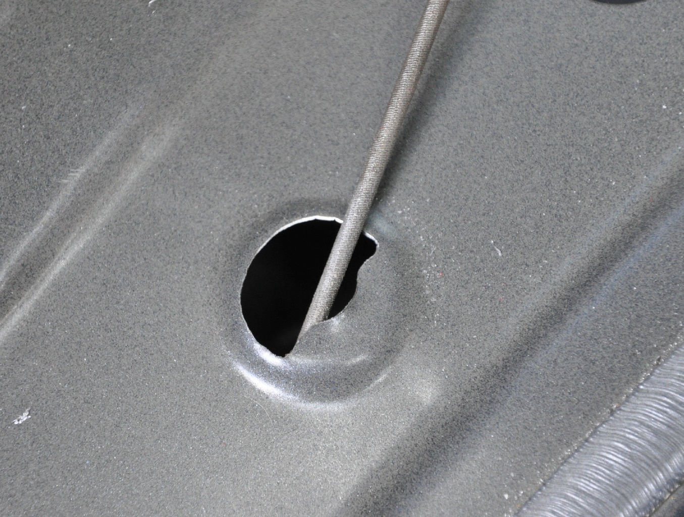 After
using the nibbler and large round file, I finished the hole with a
chain saw sharpening file to get nice smooth edge top and bottom.
|
 I vacuumed all the metal pieces from inside the hole where the bolts will clamp down.
|
 Painted inside and outside of hole with some heavy rust preventive paint.
|
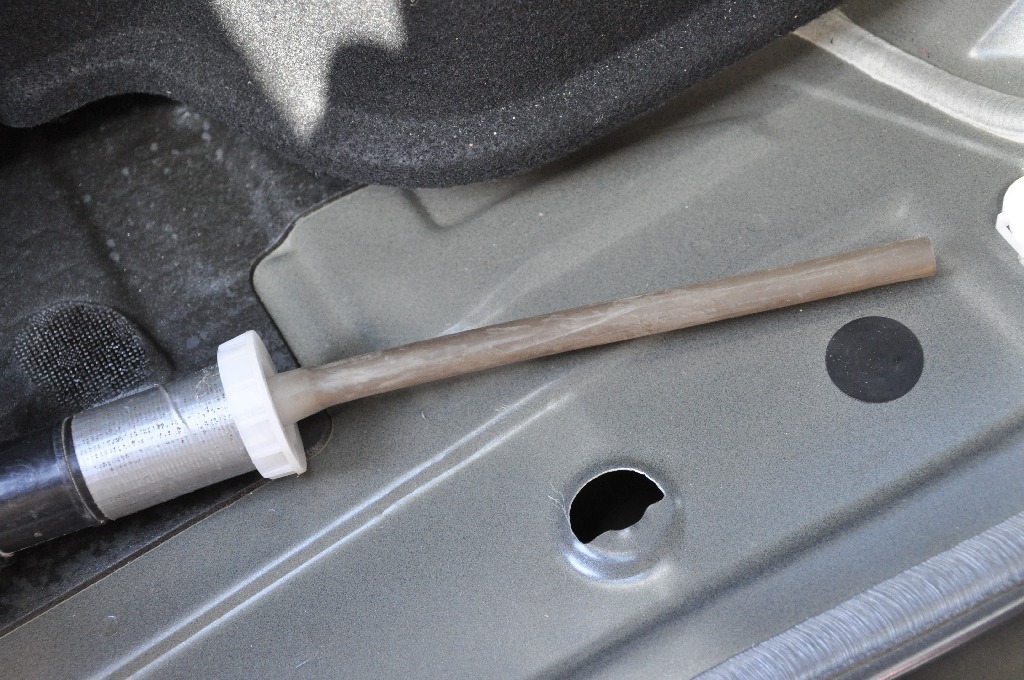
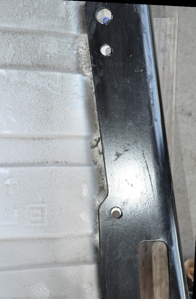
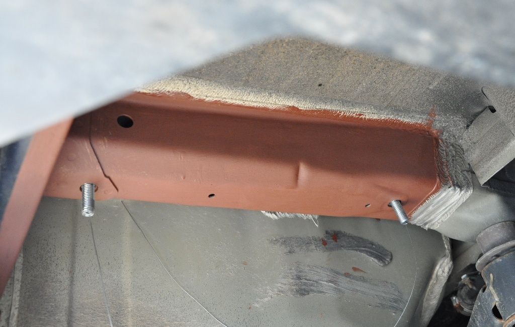
 Looking
down the enlarged top holes, the holes in the bottom of the frame box were
visible. Below them, the muffler shield was visible. I
stuck a sharpie down the hole and marked the little blue circle to indicate
where the hitch bolt will be.
|
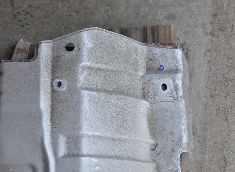
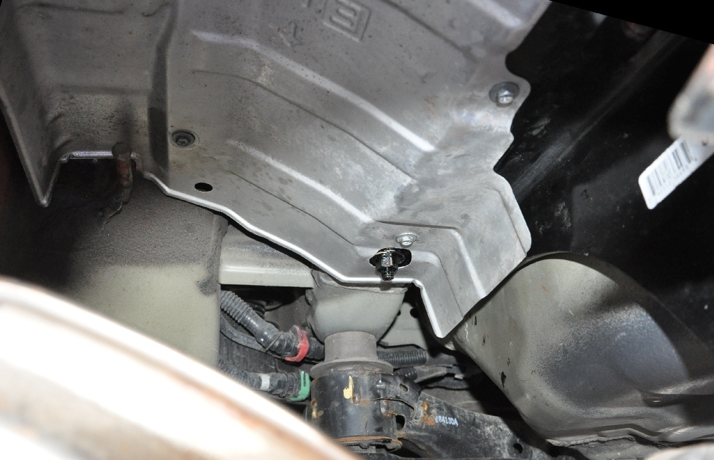
 This is how the left side muffer shield will fit on under the hitch installation. Hitch mounts to frame first, then the heat shield moslty covers the new hitch.
|
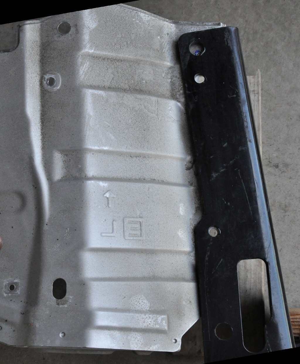
 Look
carefuly. The heat shield holes must line up with the little holes of the hitch or the shield screws won't fit back into the car
frame threaded nuts. Check this AGAIN when the hitch is hanging and before its
tightened. I had to really pressure mine into position.
When snug, I checked that the shield bolts fit loosely through the
holes with no binding. THEN I tightened the hitch bolts.
|
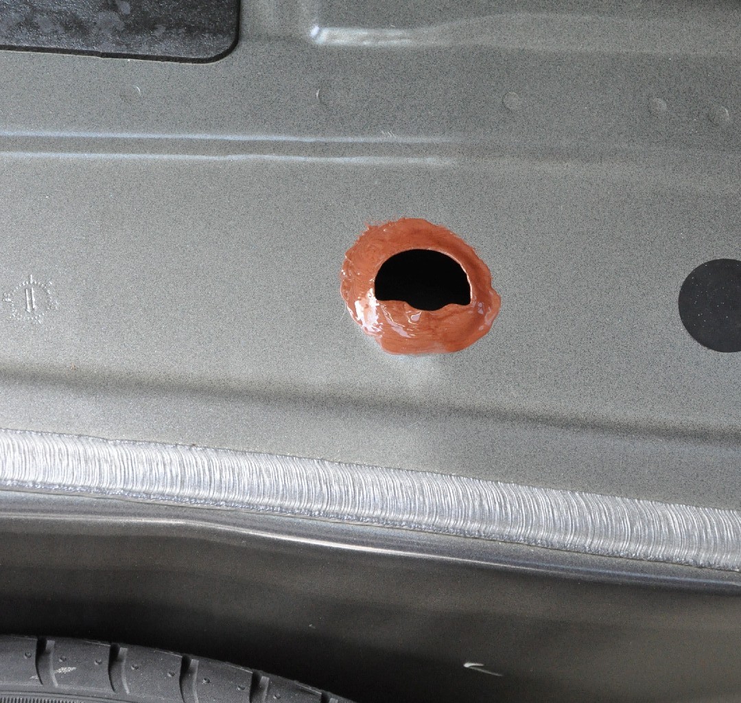
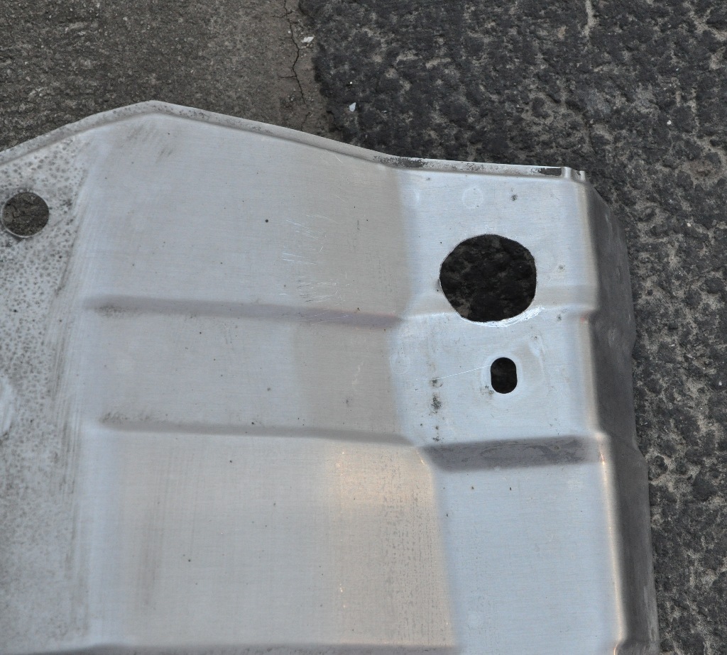 Instead
of hacking off the forward inner corner, I nibbled and filed a nice
roundish hole big enough to fit around the hitch mount nuts and washers.
|
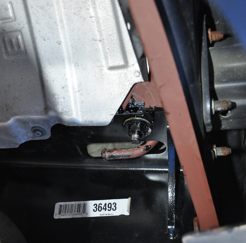
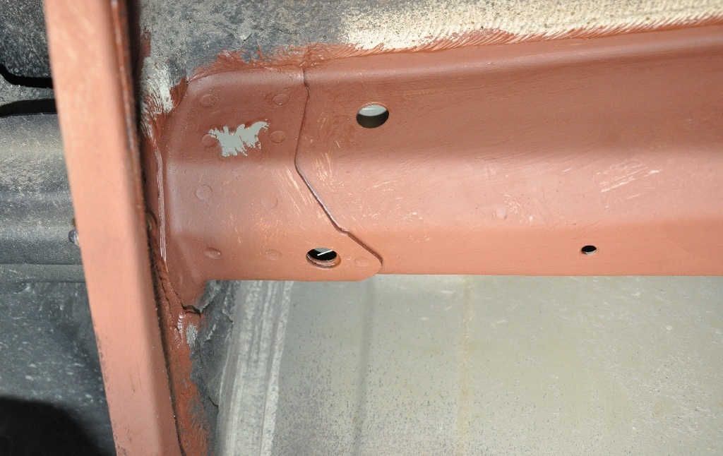 The red color is rust preventative paint I added. After drying, I fished the bolts through. Look carefully and you'll see the wire coming from the interior-forward hole to the after-under hole. There was easy 6-12" extra to poke out the hole. It was no problem to grab with a needle nose plier and pull the wire out. |
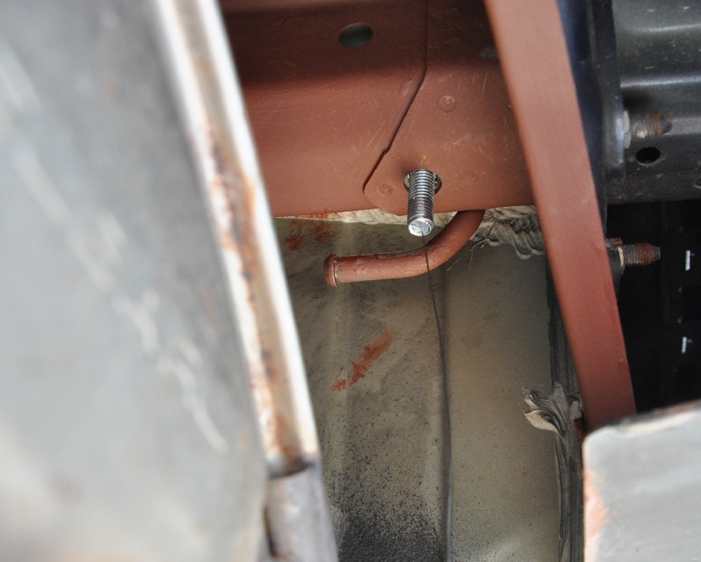 This is the bolt sticking out the aft mount hole on the left side. The muffer hangar is visible, too. In a later picture, you can see how tight the fit is after the hitch is mounted. |
 On the right side of the car, there is lots of room! Once all the bolts and fishwires are sticking out, you need another person to help lift the hitch into position withOUT pushing the bolts back, then with one hand unscrew the fish wire, put on a washer and nut. On the front two bolts, you also need to insert a spacer washer between the car and the hitch. (Or preposition it there with tape.) |
 The aft muffler hangar becomes a very tight fit after installing the hitch. |
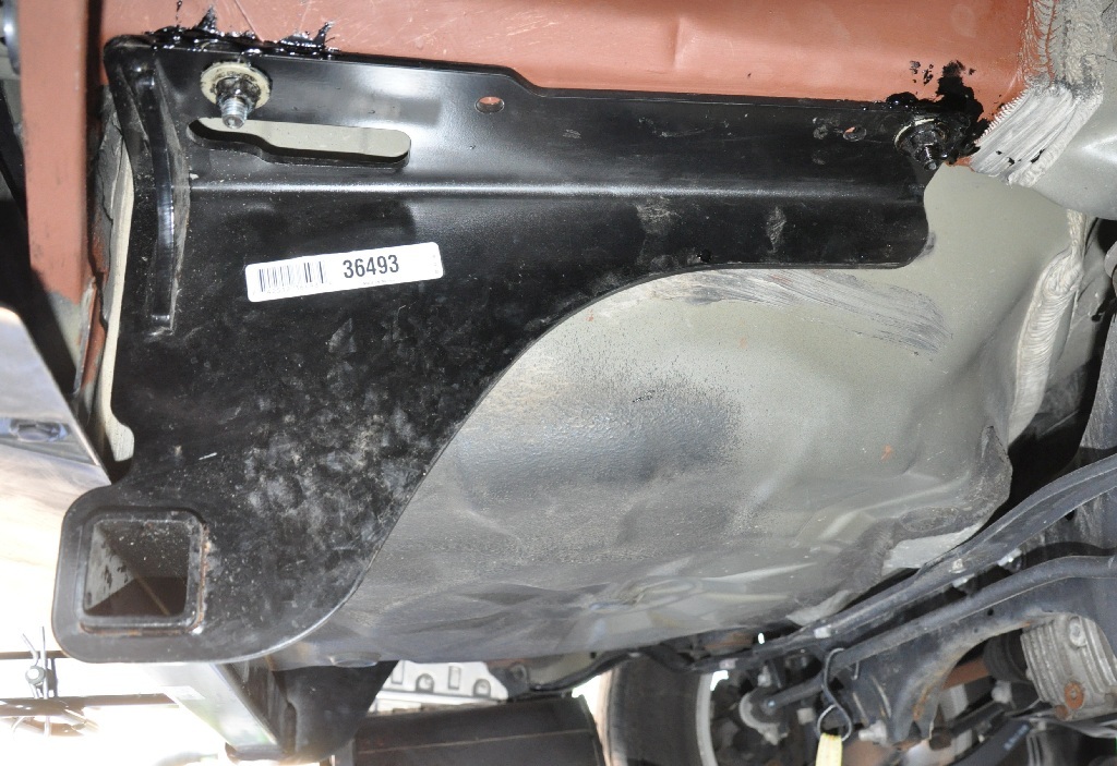
 This is how the muffler shield goes back into position, showing the circle hole around the hitch bolt. BEFORE you tighten the hitch bolts, without the heat shield in place yet, make shure the two inner heat shield bolts fit easily through the hitch pre-made holes. |
 Right side installation. Having good longevity from a previous hitch installation, I again smeared the bolt joints with thick asphalt fence paint. I think no water will get in and rust. |
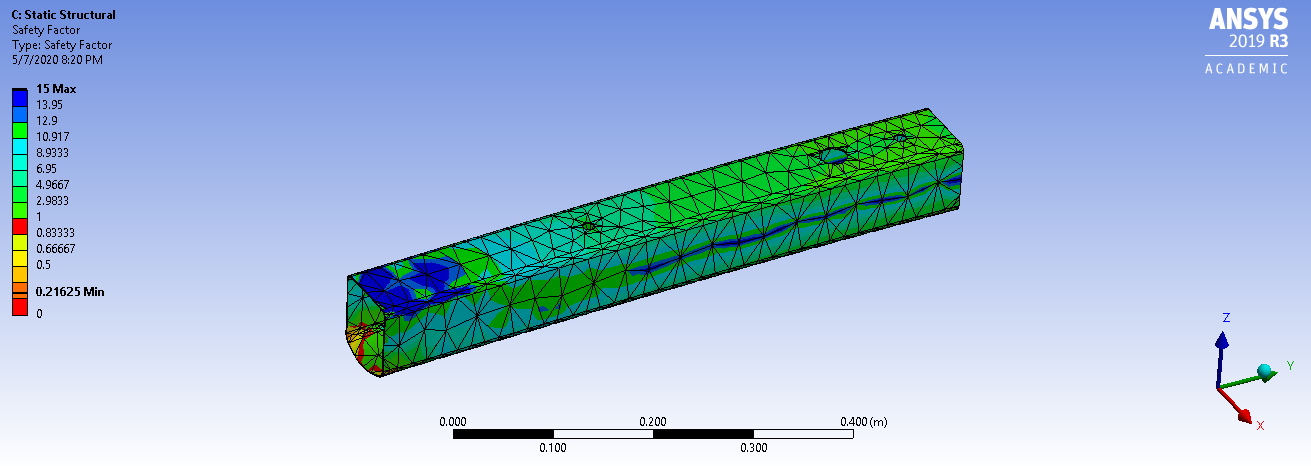
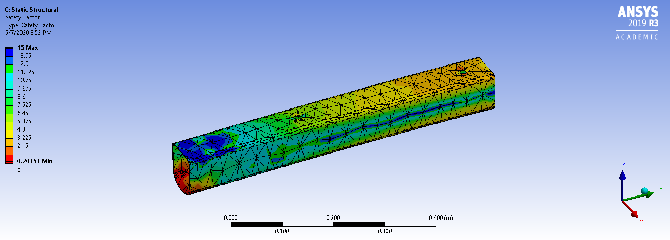 FEA analysis of aft trailer weight on frame box before drilling the access hole. This is a qualitative analysis of a heavy weight on a thicker wall box frame. |
 Enlarge the existing top forward bolt holes to 1-1/8" access (like I did for this project) seems to cause more stress around the already stressed front hole (more yellow and red color). |
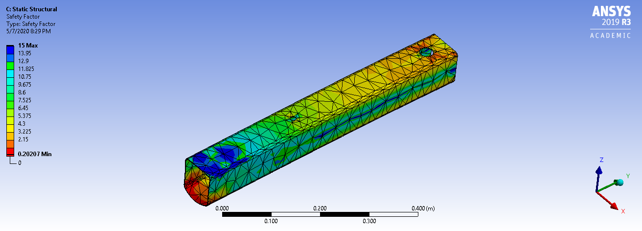
 Drill a new top 1-1/8" hole for access between the holes. Drilling another hole would have left more safety margin (less yellow and red)! Uh, yea.. this is what the instructions said but I thought I would be smarter. Uh.. nope. |