RS-232 Serial Communication and the NX-8E Home Security Alarm

Rev 1.27

© 2016-2020 Increa Technology

Site Index  •  Wiki  • Blog

 
December 2015, X.X. writes:  "Thank you for clarifying this confusing information!"
February 2018, G.S. writes, "...impressed by your depth of knowledge."
November 2020, A.S. writes, "Thank you for this page...completely makes sense" (and was kind enough to send a totally unsolicited gift of a Pi Raspberry 4 and Kookye IOT sensor kit).  Thank you!


Two Serial Options with NX-8E


The Interlogix NX-8E has two methods of doing serial communication.  One is to use the additional NX-584 board interface, the NX-587E virtual keyboard, NX-588E USB dongle interface, or the NX-586E serial dongle.  These connect onto the same DATA/+/- terminals that a user keypad uses.  The NX-584 and NX-586E each provides an electrical interface that converts to an RS-232 connection.

The second method uses a serial port on the NX-8E that does not exist on the NX-8 family or the NX-8V2.  It is a true serial port, made available on the main circuit board in the same way serial port connections were done on PC desktops circa 2005 and earlier.  As discussed below, the NX-8E has a DTK-INTEL DC-10 connector as shown in the photo below.  No electrical conversion is required - only the physical wires to bring the signals to you computer.  Here's what the connector looks like, as installed in my alarm controller box, on the lower left corner of the circuit board.


If you were to look closer, you'd see a connector like the one shown below.  Three important features are evident.
  1. One is the notch or opening on the side.  As installed, the NX-8E has this on the bottom middle.  This orients the cable the proper way when connected.  If the connector does not have a notch, or the cable does not have a key, then it's even more important to note that the red-striped wire should connect by the arrow or diamond described next.
  2. The next feature is the imprinted arrow or diamond,visible on the upper left side of the picture.  That identifies which pin is numbered 1.  The correct industry standard way to number the pins is to start by the arrow and then hop back and forth on the rows, so that in the picture, all the pins toward you are odd, and all the pins away from you are even.  In the NX-8E as normally installed in a cabinet, odd pins are toward the bottom and even pins are toward the top.
  3. The last feature is (no kidding) the 10th pin.  This is important because some cable connections have the 10th pin blocked or non-existant.  Those cables won't fit onto the NX-8E connector because the 10th pin will block it.  A correct cable connector is shown here (see it has 10 holes).
Be careful about confusing information out on the web.  Sourceforge.net gets it right, showing the pin numbering and noting that pin 1 often has a square instead of round circuit board pad.  On the other hand, bodenzord.com has the diagram labeled wrong because pin 1 is shown on the opposite side compared to the square key.  As seen in the pictures here, the pin 1 triangle is actually on the same side as the key notch. Bodenzord.com does make a good point differentiating the DTK/INTEL vs. AT-EVEREX designs.  Pinoutsguide.com gets the pinout and pin functions correct.  Github.com has a lot correct, but has directions of signals wrong - on a standard DB-9 RS-232 connector, pins 3, 4, 7 always come from the same side (the DTE equipment, such as a PC) and pins 2, 6, 8 always come from the other side (the DCE equipment).  So, for example, you'll never find DB-9 pin 2 and pin 7 coming from the same side of an RS-232 connection.

On the NX-8E, voltages of ±9 volts come out of connector IDC pins 3 and 6 (compared to common on a terminal screw or pin 9 of the IDC).  When nothing is being transmitted, pin 3 will sit at -9 volts and pin 6 will sit at +9 volts.  You need a data cable arrangement so that Pin 3 of the IDC connector makes it to Pin 2 of the DB-9 on your PC, which is where the PC is listening for data.

Your PC computer will have a DTE DB-9 serial connector presenting male pins.  So it would be nice if the cable from the NX-8E connector presented a female DB-9.  Sadly, most of the ribbon connectors are made for use inside a PC, so they also present a male connector.  You'll probably have to get an adapter with female on both sides to connect your PC to the NX-8E.


If you want to buy the official Interlogix P-0003 cable to use with this connector, they are available on the net.  However, notice the $18.54 price.
cheaper option
Pccables.com offers the required DTK-INTEL cable for $1.65 plus shipping. The pccables.com product page also has accurate connector pin numbering.  Notice the DB-9 solder connections are interleaved up and down.

I pickup a cable via eBay from China for $0.99 (including shipping), but I wasn't sure which type it was (DTK or AT). If you buy an off-brand cable, be sure to get the IDC-10 connector with 10 female holes (without one plugged). It's nearly impossible to un-plug a connector hole that has been filled with epoxy.

The cable I received from China plugged into the NX-8E header easily. It presented the NX-8E voltages on DB-9 pins 3 and 6, which means the cable I purchased was an AT-EVEREX cable (pin numbers are the same as the IDC-10 pin numbers).  Oops.  A DTK-INTEL cable needs to map IDC-10 pin 3 and 6 to the DB-9 pins 2 and 8.  In order to make my own DTK cable, I cut one of the 99 cent cables and resoldered a different DB-9 to make a DTK-INTEL cable.  I also used a female connector instead of a male connector because then it will fit directly into my PC without a gender changer.  Here's a table showing the pinout I soldered together:

Name
PC
task
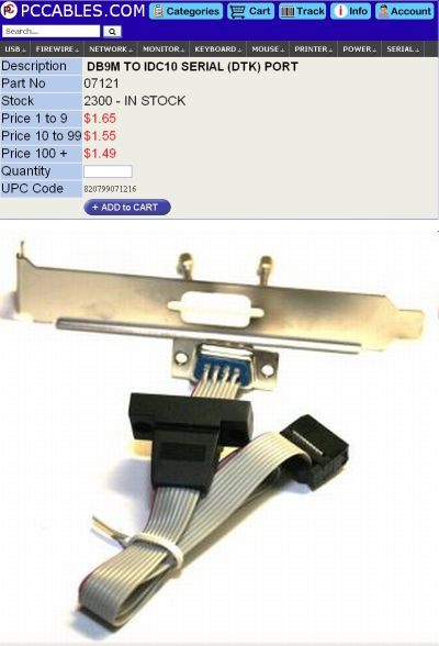
IDC 10 PIN row connector
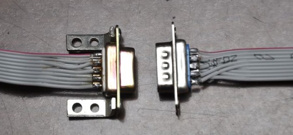
AT-EVEREX 
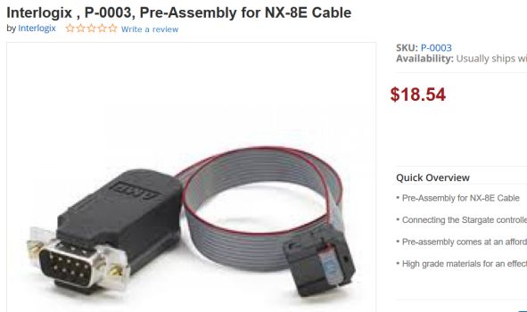
(over-under) design DB-9 pin
Move to DTK-INTEL (interleaved) design DB-9 pin to connect to PC
DCD
listen
1
1
1
DSR
listen
2
2
6
RXD
listen 3
3
2
RTS
transmit
4
4
7
TXD
transmit
5
5
3
CTS
listen 6
6
8
DTR
transmit
7
7
4
RI
listen
8
8
9
GND
-
9
9
5
n/a
n/a
10
10
n/a

Because PCs have male DB-9 connectors, I also chose to use a female DB-9 when I made my new cable.  That should allow me to use an electrically straight-through extension cable with a female on one end and a male on the other.  Notice this is different than the commerical NX-8E cable, which presents a male DB-9 (see photo above). I'm not sure if which pins present voltage when using the commerical cable.  On the

The picture below shows the new DTK-INTEL solder job I did on the left.  The square black IDC-10 connetor is off the left side of the picture.  On the right is the other AT-EVEREX cable that came with the cable.  Notice both have a certain pattern.  The DTK cable has an interleaved up/down pattern and the AT cable lays one side over the other.

DTK-vs-AT

With the DTK on the left (suitable for NX-8E), the up/down interleave at the DB-9 solder joints makes the pin numbers of the IDC and DB-9 not the same.  The AT style cable on the right, overlays left and right halves of the wires, keeping the IDC and DB-9 pin numbers the same for each wire.

Incidentally, here is one interesting memory aid that has served me for decades to remember which pins should have voltages on them for RS232-like serial connections. For DB-25 connectors:  "DTEs Transmit on Pin Two".  PCs were always Data Terminal Equipment (DTE) and modems were always Data Communicaiton Equipment (DCE) equipment.  When DB-9 connectors became popular, Pin 2 and Pin 3 reversed leaving PCs transmitting voltages on Pin 3 (TXD and RXD reversed along with other pin changes).  A PC transmits on DB-9 pins 3, 4, and 7.  Remember "3+4=7" and you've memorized all the transmit pins for a PC DTE connector!

Also, within the RS232 world, DCEs communicate with DTEs, and the pin names are from the perspective of the DTE (for example, a DCE transmits on "receive data", whereas a DTE PC connector transmits on "transmit data").   The NX-8E behaves as a DCE and transmits on Pin 2 of the DB-9, which is called the "Receive Data" pin.

Here's a picture of a DTE transmitting on Pin 3 - typical for a personal computer:

db-9 pc pinout


Turning on the NX-8E Serial Port


Here are the NX-8E programming locations used to setup the serial port to communicate with a PC terminal program. These are the settings I used for initial testing with a serial port program on my laptop computer.  Notice the documentation is peculiar becase it lists hex values when a number is required, but when configuration is a sequence of bit flags, the bits are listed in reverse order, hence 12------- would represent a hex value of 3 in that byte memory location.

You program these memory locations manually using a keypad (*8).  Here's an example for toggling between ASCII and binary mode:

* 8 x x x x  - instead of xxxx, use your programming code, which is different than normal dearm code.
0 # - select module 0 (zero)
2 0 9 # - select location 209
1 - toggle bit #1 (the MSB) to toggle between ASCII (1-------) and binary (--------)
* - save memory location
exit exit - exit programming mode

Setting bits per second rate:

* 8 x x x x  - instead of xxxx, use your programming code, which is different than normal dearm code.
0 # - select module 0 (zero)
2 0 8 # - select location 208
4 - enter binary value 4 for 38400 bps or 2 for 9600 bps.
* - save memory location
exit exit - exit programming mode


Expect that the keypad will display an error code for about 15 seconds after you exit programming mode with the EXIT key.  I think this is because it takes about that long for the changes to propagate to the alarm controller board and all the keypads in the system.

SERIAL PORT MANUAL COMMUNICATION
Loc'n Loc'n Description  Value Interpretation of Value
207 Serial Port Enable 01h
Home Automation Protocol
208 Serial Port Baud Rate 02h
9600 bps
209 Home Automation Protocol (vice printer) 1-------
ASCII mode
210(1) NX-8E Transition-Based Broadcasts Enable flags (NX-8E automatically sends) -2--5-7-

Configuration, Zone Status, & Partition Status
210(2) " 12------ System Status, X-10 Messages Received
211(1) NX-584 Command Request Enable flags (NX-8E responds to these message types). -2-45678


Interface Config, Zone Name, Zone Status, Zones Snapshot, Partition Status, Partitions Snapshot
211(2) " 123----- System Status, Send X-10 Message, Log  Event
211(3) " -------- none
211(4) " ---4--7- Set Clock Calendar, Secondary Keypad Functions

Once the NX-8 is configured to use the serial port, you need to consider what program you will use on your PC to talk to it.  Here are several options.

You can hook your Windows PC to the NX-8E using the Hyperterminal program, or equivalent.  If you're unaware, Hyperterminal came for free with Windows prior to Windows 7.  You can still get Hyperterminal on Windows 10 if you have a copy of Windows XP install media.  Or, if you have a copy of Windows XP running, look in the C:\Program Files\Windows NT directory and take a copy of the Hyperterminal program.  If you do this, also grab the Hyperterminal dll out of the \Windows\System32 directory.

On a Windows PC, if you'd like a clean stand-alone option to replace Hyperterminal, consider using PuTTY in the serial communication mode.

On a mid-2007 MacBook running 10.5.8 Leopard (and others I presume), connection to a serial port can be done with a USB/serial converter cable and drivers that come with the cable.  It seems the simplest software to do this is the built-in command line "screen".

whitey:~ admin$ ls /dev/*usb*
/dev/cu.usbserial    /dev/tty.usbserial
whitey:~ admin$ screen /dev/tty.usbserial 9600

{The terminal screen clears and you're talking out the serial port. Cntrl-A initiates commands to the screen program; otherwise whatever you type goes to the serial port. Cntrl-\ exits the screen program back to the Terminal command line. 
To learn more, type "man screen" at the Mac Terminal command line.}

I have used the Darwin Port (now MacPort) program Minicom and the classic Kermit program which also installs when you install Minicom.  You can also download Kermit from the Mac App Store. Kermit has been around since 1982, and available for almost every computer platform known to man. I'm sure it's been overrun by better options, but it is very historical, stable, universal - almost the ultimate retro choice.  It also allows fancy scripting and logging.

In 1997, I used Kermit on the ground station of receiving satellite telemetry data.  I've used it for amateur radio digital communication.  Now, I'm using Kermit to talk with my NX-8E security system. Once installed onto your Mac, from the command line here's how I bring it up on a mid-2009 MacBook Pro running 10.6.8 (snow leopard):

bmmbp:~ name$ ls /dev/*usb*
/dev/cu.usbserial    /dev/tty.usbserial
bmmbp:~ name$ kermit
C-Kermit 9.0.302 OPEN SOURCE:, 20 Aug 2011, for Mac OS X 10.6.8 (64-bit)
 Copyright (C) 1985, 2011,
  Trustees of Columbia University in the City of New York.
Type ? or HELP for help.
(/Users/name/) C-Kermit>set line /dev/tty.usbserial
(/Users/name/) C-Kermit>set carrier-watch off
(/Users/name/) C-Kermit>set speed 9600
/dev/tty.usbserial, 9600 bps
(/Users/name/) C-Kermit>set session-log text
(/Users/name/) C-Kermit>log session kermitlog.txt
(/Users/name/) C-Kermit>connect
Connecting to /dev/tty.usbserial, speed 9600
 Escape character: Ctrl-\ (ASCII 28, FS): enabled
Type the escape character followed by C to get back,
or followed by ? to see other options.
----------------------------------------------------

{Nothing was hooked up so no data appears here; I typed Cntrl-\ and c on the keyboard}

(Back at bmmbp.local)
----------------------------------------------------
(/Users//) C-Kermit>exit
Closing /dev/tty.usbserial...OK
bmmbp:~ name$

If you'd like a small form-factor computer, try a Raspberry Pi/3 computer, which has a USB port that will talk serial with the addition of a $15 adapter, plus it has built in wireless internet, all about the size of a 5x7 card.  It runs on about 2 amps of 5 volt power, available inside the NX-8E cabinet.  The Raspberry Pi runs a full version of Linux or other operating systems, and you don't need a keyboard or mouse because you can SSH to the Pi or run a VNC server on the Pi.  This means you can sit at your desktop computer in another place in the world and remotely use the Pi computer as if you were sitting there with a monitor and keyboard.  This, of course, is programmable in any language you like that will load on the operating system you choose.

As one last interesting observation, the 1980s era Sharp EL-550 calculator has a serial port (but not RS-232) that can hook to the NX-8E.  It also has a fully functional BASIC (computer language) interpreter and runs on two little batteries that last for years.  This makes me think of all sorts of remote automation ideas. This could be a supervisory computer that monitor mechanical health and welfare and status of the NX-8E.

Lastly, one caution.  If you hook up a computer and then make that computer available from the internet, there may be a security issue.  Most NX-8E operations over the serial port can be done without a security PIN number. This is a good way to recover an alarm system that is locked up with a PIN you don't know.  However, by exposing the interface on the web, the web access will also not need a PIN. 


Protocol of the Serial Port


Once serial communication, it's worth considering what commands or data can be transmitted.  The NX-8E built-in serial port capability uses the same Caddx protocol for the NX-584 RS-232 Gateway protocols (local copy). Here's the first data I logged that the NX-8E spits out, unsolicited:

(/Users/name/) C-Kermit>connect
Connecting to /dev/tty.usbserial, speed 9600
 Escape character: Ctrl-\ (ASCII 28, FS): enabled
Type the escape character followed by C to get back,
or followed by ? to see other options.
Session Log: /Users/name/kermitlog.txt, text (0)
----------------------------------------------------

098600380008400104809553
098600380008400104809553
098600380008400104809553
098600380008400104809553
098600380008400104809553
(Back at bmmbp.local)
----------------------------------------------------
(/Users/name/) C-Kermit>

Each message starts with a LF character and is terminated with a CR.  These are displayed on most terminal programs as a (surprise!) carriage return to the beginning of the line and a line feed to the next blank line.   The data message repeated above is interpretable as:

09 - Msg Len - 9 more bytes in the message
86 - Byte 1 - Top bit indicates an Ack is required. Bottom 6 bits indicate Message #06 - Partition Status Msg
00 - Byte 2 - Partition number (0=partition 1)
38 - Byte 3 - Partition condition flags ---345--: Pulsing buzzer, TLM fault memory, Reserved
00 - Byte 4 - Partition condition flags --------: no flags set.
08 - Byte 5 - Partition condition flags ---3----: Entry
40 - Byte 6 - Partition condition flags ------6-: Sensor Low Battery
01 - Byte 7 - Last user number: 1
04 - Byte 8 - Partition condition flags --2-----: Ready To Arm
80 - Byte 9 - Partition condition flags -------7: Delay Trip in Progress (common zone)
Checksum 95 and 53 can be checked with a spreadsheet checksum calculator.

Just to keep things interesting, notice the NX-8E programming manual numbers bits 1-8, and the serial protocol numbers bits 0-7.

According to the protocol documentation, "When the Ack-Req'd flag is set, the message must be acknowledged or the same message will be repeated."  And sure enough, that's what is happening. The NX-8E is looking for a positive ack in the form of the Positive Ack message, message 1Dh.  Contructed as 0A 01 1D 1E 1F 0D.  On a terminal, this is Cntrl-J Cntrl-A Cntrl-] Cntrl-^ and Cntrl-_ Cntrl-M (or CR).

When I changed location 210 to all zeros or just keep bit 5 set in byte 1 (requesting Zone Status Messages), nothing changes.  Hmmm..  the Partition Status Msg is still produced.  In fact programming location 210 seemed to have no effect to generate more or less data.  I wonder if the whole system needs to be powered off/on to make the serial port behave differently.


Connect Software to the Serial Port


If you're hooking up the NX-8E to a specific piece of software or hardware like DL-900 or HomeSeer, you should make sure the programming locations are all set properly for that piece of software or hardware that you are using.  Over on the micasaverde.com forum, I found recommended settings for using the DL-900 program:

SERIAL PORT DL-900 COMMUNICATION
Loc'n Loc'n Description  Value Interpretation of Value
207 Serial Port Enable 01h
Home Automation Protocol*
208 Serial Port Baud Rate 04h
31600 bps
209 Home Automation Protocol (vice printer) --------
Binary mode
210(1) NX-8E Transition-Based Broadcasts Enable flags (NX-8E automatically sends) -2--5678

Intf Cfg at pwr up, Zone Status, Zones Snapshot, Partition Status, Partition Snapshot
210(2) " 1-34---- System Status, Log Event Msg, Kpd Msg Rcvd
211(1) NX-584 Command Request Enable flags (NX-8E responds to these message types). -2-45678


Interface Config, Zone Name, Zone Status, Zones Snapshot, Partition Status, Partitions Snapshot
211(2) " 1-345--- Sys Status, Log Event, Kpd Txt, Kpd Term Mode
211(3) " 123-5-7- Pgm Data Rqst, Pgm Data Cmd, User Info Rqst w/PIN,Set Usr Code w/PIN, Set User Auth Cmd w/PIN
211(4) " --345678 Stor Comm Event Cmd, Set Clk/Calendar, Primary Kpd Func w/PIN, Prim Kpd Func wo/PIN, Sec Dpd Func, ZoneBypass Toggle
* notice in this context "NX-584" mode (in some documentation) is the same as Home Automation Mode.  The other alternative is printer mode. This is an imprecise left over from older systems that required the NX-584 interface because theydid not have a dedicated serial port like the NX-8E.


The DL-900 program is available for free.  This program is meant for an alarm system installer or technician who has to manage alarm profiles at a number of customer locations.  You'll have to create a customer profile for yourself and then access your NX-8E using that profile.

I confirmed everything was working through a Hyperterminal connection at 38,400 bps ASCII mode while using a USB to serial port cable.  I closed the connection, shut down Hyperterminal, and used the DL-900 to make an ASCII connection.  It took a few false starts, a couple of "can't talk to module 0" error messages, a computer rebooot and then the DL-900 was able to connect.  Using ASCII mode, it took a long time (minutes) to download all the programming data from the NX-8E.  I switched the DL-900 to binary mode and used a keypad to change the NX-8E to binary mode. 
I'm hooked.  It's a lot easier to program the alarm system with the DL-900 software.  It can print several different types of reports including a 29-page dump of every setting in the NX-8E and attached keypads.  Now I also have a software config file for my alarm -- no need to write down all the memory locations and enter data through the keypad :-)


Additional Resources

  1. EL-5500 on promsoft.com
  2. Hacking the Sharp EL-5500 calculator
  3. NX-8E Checksum Calculating Spreadsheet
  4. Caddx Serial Communication Protocol (local copy)
  5. nxgipd - a monitoring daemon for UTC Interlogix / GE Security / Caddx NetworX series alarm systems

Valid HTML 4.01 Transitional


The skeleton of this document was originally created using AbiWord under a Gnome desktop.  It was subsequently edited by Konquerer to become the web page you are reading.  Created October 2016. Last updated November 2020.  The best way to get hold of me is via email.