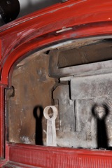
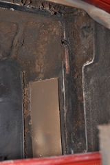
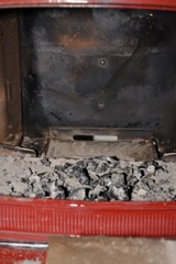
Picture #1 - This shows the two front log blocking posts, the metal wedges on left and right side, the fireback is in place, the two side panels are in place and the rod-hanging pivot scoop is in place. In the shadows at the inside top of the stove is the flue where the hot flames go in non-catalytic mode.
First step is to remove the two posts that block logs from falling against the front glass windows. I used an 11 mm socket, but I think the bolts are intended to be 7/16” (7/16” is 0.1/16” larger than 11 mm). You just have to loosen the bolts and then the posts slide upward to come out.
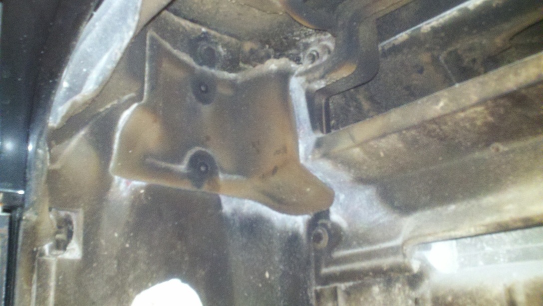
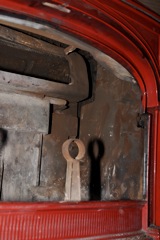
Picture #2 – This shows the side plate that must be removed to take out the heavy metal flue flapper box. Bottom bolt is visible in the shadow of the log post. The top bolt is not visible in this picture, hiding behind the red upper lip of the door. 7/16” or 11 mm socket will work.lt, although I used an 11 mm socket.
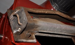
Picture #3 – This shows the two bolts that have to be removed to take out the right side (as looking at the stove) side plate. It may be possible to not remove this plate and still change the catalytic box, but clearances may not be enough The bottom bolt is visible just above the red bottom lip of the door frame. The top bolt is ½ visible just under the curved red door frame. 7/16” bolt.
Picture #4 - Look in the back of the stove and lightly tap upward on the two metal wedges on the left and right side. Once they are loose and removed, the fireback will freely tilt forward toward you. Remove. The picture above shows the normally non-visible back side of the fireback plate.
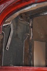
Picture #5 - This shows the left side looking into the stove where the heavy metal flue flapper box was attached. One bolt per side. The fit is very awkward. See two horizontal slider protrusions. The flapper box has to be fit onto these and pressed against the back wall of the stove, plus it's very heavy. Re-installing this piece probably requires 2 people. Look carefully to see the bolt hole through which the 7/16” (11 mm) bolt is removed from the back exterior of the stove. See also the angular arm that connects the flue flappy handle to the flue flapper. Once you disconnect this arm, the heavy metal flapper will have a tendency to rotate down and pinch fingers or hit the catalytic box.
Picture #6 - This shows the right side looking into the stove. You can see the flat flange that the flapper box fits against and the bolt hole through which the 7/16 (11 mm) bolt fits from the outside of the stove. When removing the heavy metal flapper box, the right side will come loose and lower first. Rotate it down and toward you as you squat in front of the stove. Then the left side will pull away from the interior of the stove.
Picture #7 - This is the left side of the flue flapper box – by far the most difficult to remove and replace part of the job. See the two molded iron protrusions? They have to fit into grooves molded into the stove itself.
Picture #8 - After you remove the heavy flue flapper box, you will be able to freely lift out the catalytic converter box. Wait! Before you try to remove the box, unscrew the stainless steel panel on the back of the stove and remove the auto-damper and the mounting screw for the temperature spring. Gently pull the temperature spring and the temperature probe straight out the back. When re-installing the new flew box, use a drill and handle-wiggle a hole through the mounted catalytic box to receive the temperature probe.
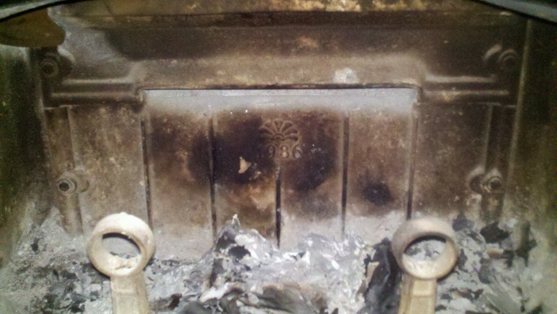
Picture #9 - The catalytic converter
access panel is designed to allow easy replacement of the catalytic
convertor. The silver catalytic converter shown in this picture is
fine, even after 15 years.
To get a long life, be sure to start fires directly up the chimney
(flapper open) until the stove is hot and the logs are "burning
clean". When adding new logs, open the flapper until the loose
stuff is burned away.
I slide the catalytic converter out and slid it
into place in the new flew box.
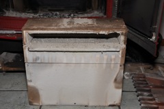
Picture #10 - This is what the back of the stove looks like after you removed the catalytic box. The little slot in the back is the auto-damper where fresh air can come in under the box for combustion. Be sure to clear out all ash from all areas around the box, and out of the groove that the fireback plate will drop back into. Uhh.. yea.. I didn't clean out all the ashes and charcoal; I sort of just swept it into a pile in the middle. It would be better if you cleaned this all out before even starting the project.
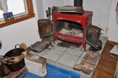
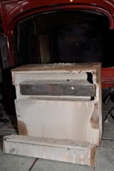
Picture #11 - Overall project view
when ½ done (taken apart).
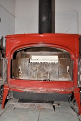
Picture #12 - In this picture, the new catalytic box has been replaced, the heavy flue flapper box has been replaced, and the firebox back has been set into place and is tilting forward. When the two side panels are replaced (two bolts each), then the wedges will be used to hold the fireback firmly against the new catalytic box. The rod-hanging air scoop has not yet been replaced. I found that sliding the left hinge in first, and then sliding the entire assembly to the right lets the hanging bars engage properly.
Picture #13 - Lastly, don't forget to put the temperature probe back in the the back of the stove. I used a small drill and rotated it with my finger to gently make a hole in the new catalytic box for the temperature probe.