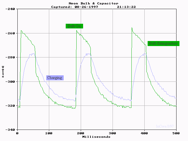
These waveforms were taken under unique conditions. I tried to hook the oscilloscope ground to the negative side of the battery and hook the scope probes onto the circuit (similar to how I took all the other waveforms). Because of the tremendously high impedance of the circuit (about 4 Megaohms), even the 10 Mohm scope probes loaded the circuit enough so that the capacitor never got charged. In essence the scope itself was shorting the capacitor to ground! So.. I hooked the battery powered scope ground to the charging power supply (-300 VDC in this case, measured simultaneously with a DVM), and took relative voltage readings for the capacitor and the neon bulb. I used a spreadsheet to subtract 300 from each voltage reading, and then plotted this graph. The green trace, with the nearly instantaneous jump toward ground, is the voltage across the neon bulb, while the blue trace is the voltage on the 0.002 uf capacitor.

One artifact of this method, however, is recorded voltages as low as -322 volts, even when the power supply was only -300 VDC. This happens because the capacitor will not sustain a long-term DC voltage across it; charge is slowly leaked off the bottom side, into ground, until both sides of the capacitor average about -300 volts. Integrating either trace above and below -300 V (the psuedo ground) should give zero. Doing this with my scope shows the integral of voltage across the neon bulb and the capacitor is, indeed, zero.